voltage generator

A technology of voltage generators and voltage regulators, applied in instruments, regulating electrical variables, control/regulating systems, etc., can solve problems such as unstable work and affecting work efficiency

Active Publication Date: 2022-07-05
WINBOND ELECTRONICS CORP
View PDF7 Cites 0 Cited by
  • Summary
  • Abstract
  • Description
  • Claims
  • Application Information

AI Technical Summary

Problems solved by technology

This period of stabilization time will cause the load 506 to work unstable for a certain period of time, which will affect the work efficiency.

Method used


Image

  • voltage generator
  • voltage generator
  • voltage generator

Examples


Embodiment Construction

[0042] Hereinafter, embodiments of the present invention will be described with reference to the drawings.

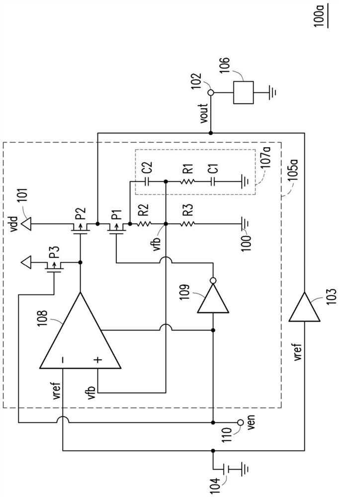
[0043] figure 1 It is a circuit diagram of the voltage generator 100a of 1st Embodiment of this invention.

[0044] The voltage generator 100a of this embodiment includes a ground terminal 100, a power supply terminal 101, an output terminal 102, a first voltage regulator 103, a reference voltage source 104, and a second voltage regulator 105a, wherein the second voltage regulator 105a includes an initial voltage The generator 107a, the error amplifier 108, the inverter 109, the enable signal input terminal 110, the transistors P1, P2 and P3, the first resistor R1, the second resistor R2 and the third resistor R3, and the first capacitor C1 and the The second capacitor C2.

[0045] The connection relationship of the above components is as follows: one end of the reference voltage source 104 is connected to the inverting input terminal of the error amplifier 108 and t...


PUM


Abstract

The present invention provides a voltage generator, comprising: a first voltage regulator, which supplies an output voltage to an output terminal according to a reference voltage; a second voltage regulator, which decides to operate in an enable mode or a disable mode according to an enable signal, when the first The two voltage regulators operate in the enable mode to supply an output voltage to the output terminal according to the reference voltage; and the initial voltage generator, when the enable signal switches the second voltage regulator from the disable mode to the enable mode, the initial The voltage generator keeps the feedback voltage of the second voltage regulator at an initial voltage value close to the reference voltage, so that the feedback voltage of the second voltage regulator can be quickly locked to the reference voltage and reduce the settling time and overshoot voltage of the output voltage.

Description

technical field [0001] The present invention relates to a voltage generator. Background technique [0002] Figure 5 A circuit schematic diagram showing a prior art voltage generator 500c. [0003] After the second voltage regulator 505c is switched from the disable mode to the enable mode through the enable signal ven, the feedback voltage vfb of the second voltage regulator 505c must be re-locked to the reference voltage vref, and the feedback voltage vfb is locked to the reference voltage vref A certain length of time tc (called the settling time) that the process takes, such as Image 6 shown. This stable time will cause the load 506 to work unstable for a certain period of time, which will affect the work performance. SUMMARY OF THE INVENTION [0004] The present invention provides a voltage generator which can reduce the settling time of the output voltage and the amplitude of the overshoot voltage (positive overshoot or negative overshoot). [0005] An embodimen...

Claims


Application Information

Patent Timeline
Patent Type & Authority Patents(China)
IPC IPC(8): G05F1/575
CPCG05F1/575
Inventor 佐藤贵彦
Owner WINBOND ELECTRONICS CORP
Why Eureka
Try Eureka