Oil gas recovery system and method
An oil and gas recovery system, oil and gas technology, applied in separation methods, chemical instruments and methods, and dispersed particle separation, etc., can solve problems such as high recovery costs, difficult operation, complex structure, etc., achieve good oil blocking effect, low separation cost, The effect of simple system structure
- Summary
- Abstract
- Description
- Claims
- Application Information
AI Technical Summary
Problems solved by technology
Method used
Image


Examples
Embodiment 1
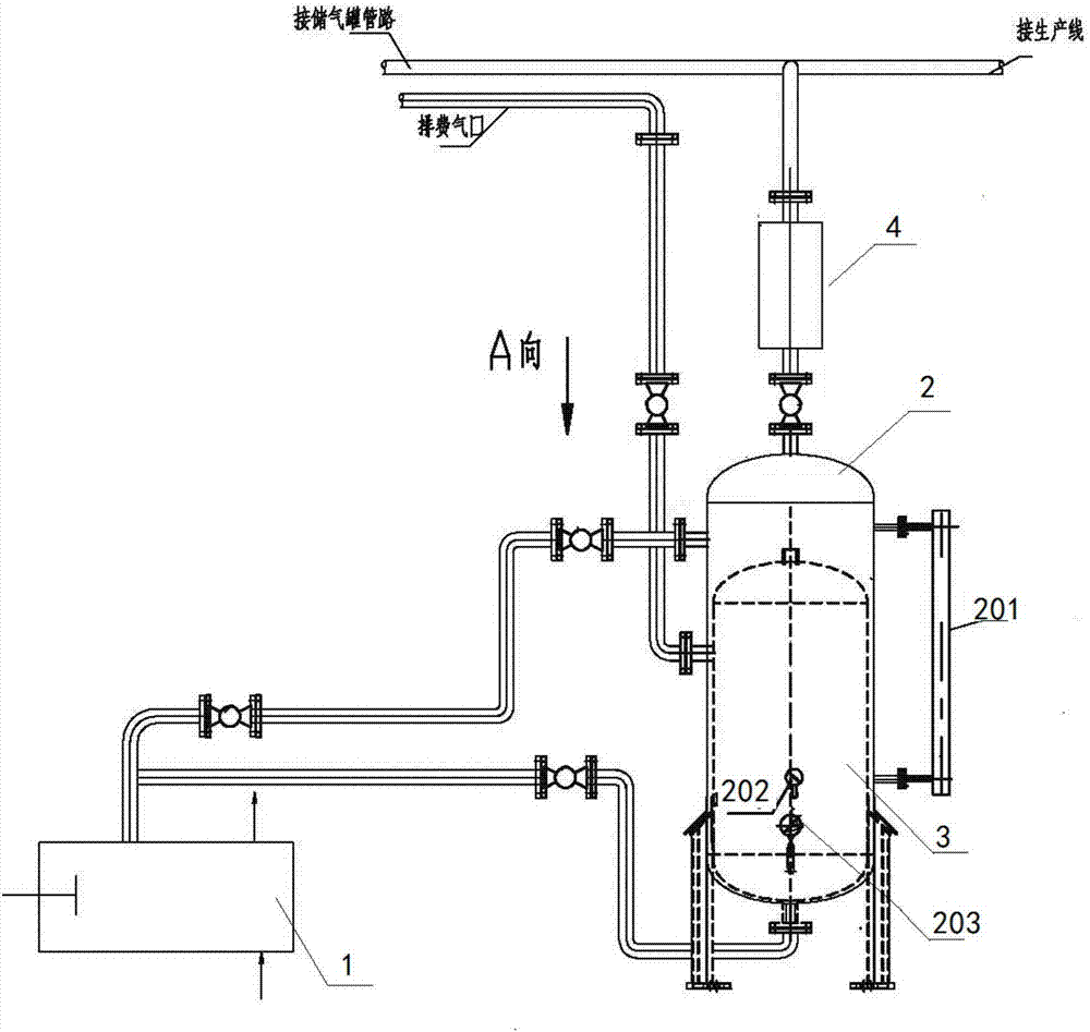
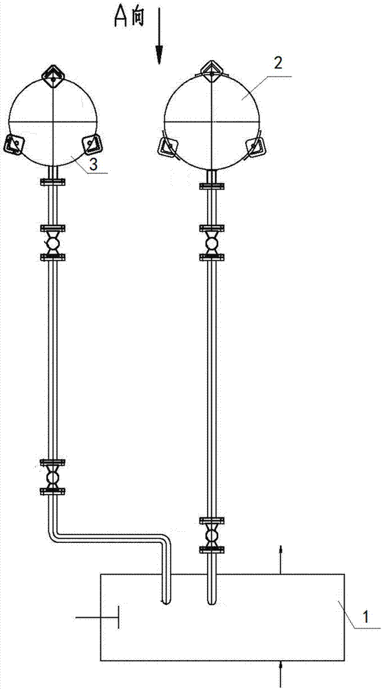
[0040] Such as Figure 1-7 As shown, an oil and gas recovery system includes a vacuum pump 1, a recovery tank 2 and a filter tank 3. The vacuum pump 1 is respectively connected to the recovery tank outlet 204 of the recovery tank 2 and the air inlet 304 of the filter tank 3, and the recovery tank inlet of the recovery tank 2 is 203 is connected to the external production line pipeline and gas storage tank pipeline through the return device 4, and the gas outlet 305 of the filter tank 3 is connected to the exhaust gas outlet.
[0041]The recovery tank 2 is provided with a liquid level gauge 201, and the liquid level gauge 201 is arranged vertically. Through the liquid level gauge 201, it is convenient to see the amount of recovered oil in the recovery tank, which is convenient for recovery operation. The top of the recovery tank 2 is the recovery tank inlet 203, and the oil gas enters the air supply pipeline through the recovery tank inlet 203 to send the waste gas into the rec...
Embodiment 2
[0046] Embodiment 2 is basically the same as Embodiment 1, except that the recovery tank 2 is provided with a pressure gauge interface 209 and a thermometer interface 210, which are respectively connected to the pressure gauge and the thermometer. You can also choose one of them to connect, which is convenient for monitoring the pressure and temperature in the recovery tank.
Embodiment 3
[0048] A recovery method for an oil and gas recovery system, the steps are as follows:
[0049] A. Turn on the vacuum pump 1, the vacuum pump 1 generates negative pressure, and open the valve of the recovery tank 2 line;
[0050] B. The waste gas and tail gas of the production line pipeline and the gas storage tank pipeline enter the choke 4 through the valve and then enter the recovery tank 2. The recovery tank 2 absorbs and recovers the oil and gas, and the recovered gas enters the vacuum pump 1;
[0051] C. Due to negative pressure, open the valve of the filter tank 3 line, the gas of the vacuum pump 1 in step B enters the filter tank 3 through the pipeline, and detects through the sampling port. After reaching the discharge standard, open the gas outlet 305 valve and pass through the high-altitude The exhaust pipe goes into the atmosphere.
[0052] The above method effectively recovers oil and gas, and prevents the backflow of oil and gas, which is convenient and quick, a...
PUM
 Abstract
Description
Claims
Application Information