
Clamping system and clamping method for large similar cylindrical workpieces

A cylindrical workpiece and workpiece clamping technology, applied in workpiece clamping devices, metal processing mechanical parts, clamping and other directions, can solve the problems of poor flexibility, hinder workpiece clamping operation, inconvenient operation, etc., to avoid collision and friction damage, Increase the effective contact area and avoid local damage

Pending Publication Date: 2017-10-24
重庆真测科技股份有限公司 +1
View PDF20 Cites 9 Cited by
  • Summary
  • Abstract
  • Description
  • Claims
  • Application Information

AI Technical Summary

Problems solved by technology

[0002] With the rapid development of science and industry technology, industrial manufacturing technology has made revolutionary breakthroughs, and the performance of corresponding processing and manufacturing, testing, experiment and other equipment has become stronger and stronger, but the clamping process of supporting workpieces or parts has not Adaptive progress has been made. With the implementation of various large-scale projects, the demand for clamping, processing, testing, moving, and fixing of large parts and components has become increasingly prominent. The traditional workpiece clamping method is not efficient and inconvenient to operate. Difficult to meet requirements
For example, when the entire large cylindrical workpiece is clamped, fixed, moved, hoisted, and integrally rotated, there are many problems: inconvenient operation, poor flexibility, lack of safety, poor precision, high cost, and low efficiency; some clamping devices It is suitable for the clamping of cylindrical workpieces with regular shapes. It can be clamped by trapping the workpieces at both ends respectively; but in the actual operation process, due to the large volume and weight of the workpieces, the process of inserting them is not easy, especially the workpieces When there are special-shaped structures such as "wings" locally, it hinders the clamping operation of the workpiece; and during the clamping operation, it is easy to cause damage to the surface of the workpiece; in order to solve this problem, it is necessary to conduct in-depth research

Method used


Image

  • Clamping system and clamping method for large similar cylindrical workpieces
  • Clamping system and clamping method for large similar cylindrical workpieces
  • Clamping system and clamping method for large similar cylindrical workpieces

Examples


Embodiment Construction

[0038] The technical solutions in the present invention will be further described below in conjunction with the accompanying drawings and embodiments.

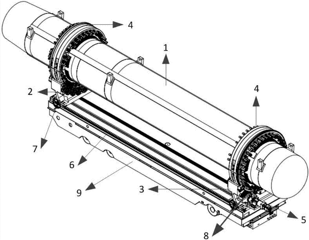
[0039] Clamping systems for large, nearly cylindrical workpieces, such as figure 1 As shown, the bearing platform 9 is included, and the first support base 3 and the second support base 2 for supporting the fixed and rotating workpiece clamping device 4 are arranged in parallel on the bearing platform 9 .

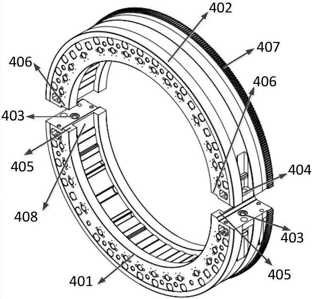
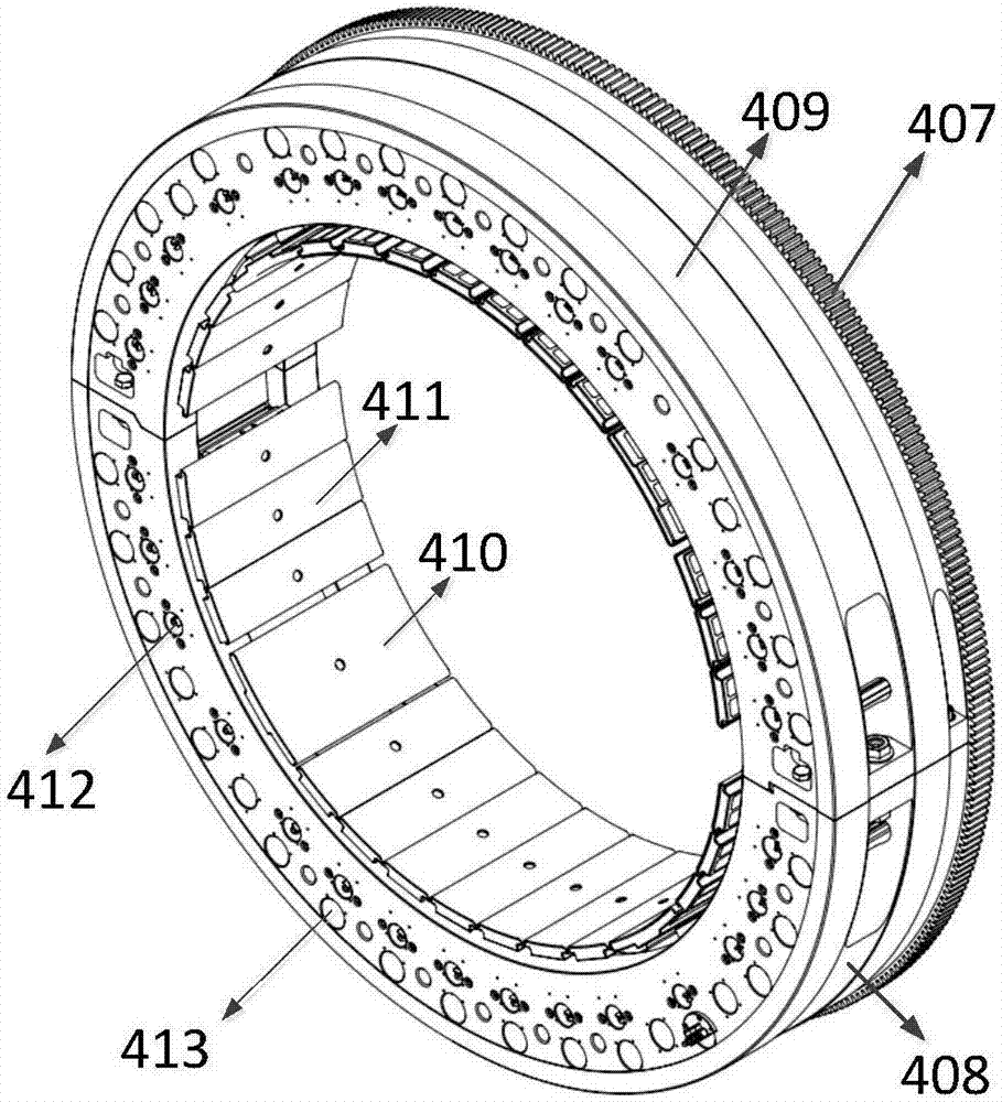
[0040] Such as figure 2 , image 3As shown, the workpiece clamping device includes a first fixture body 401 and a second fixture body 402 in a semi-circular structure, and the first fixture body and the second fixture body can be relatively connected to form a workpiece in a complete circular structure Integral clamping device; along the outer edge of the ring structure, the same side edges of the first clamp body and the second clamp body are also provided with transmission teeth 407 for meshing with external gears; on ...


PUM


Abstract

The invention provides a clamping system for large similar cylindrical workpieces. The clamping system comprises at least two workpiece clamping devices; the workpiece clamping devices comprise first fixture bodies with semicircular structures and second fixture bodies; the first fixture bodies and the second fixture bodies are relatively connected to form a complete ring structure; and along the outer edge of the ring structure, transmission teeth engaged with external gears are arranged on the edges of the same side surfaces of the first fixture bodies and the second fixture bodies. The clamping system further comprises a bearing platform, and support bases arranged on the bearing platform in parallel; and a rotary driving device is arranged on one support base, and comprises a rotary driving mechanism and a driving gear connected with an output shaft end of the rotary driving mechanism. The invention further provides a clamping method for the large similar cylindrical workpieces. The clamping system has the advantages of safety, reliability, convenience in operation and high adaptability.

Description

technical field [0001] The invention relates to the field of fixtures, in particular to a clamping system and a clamping method for a large near-cylindrical workpiece. Background technique [0002] With the rapid development of science and industry technology, industrial manufacturing technology has made revolutionary breakthroughs, and the performance of corresponding processing and manufacturing, testing, experiment and other equipment has become stronger and stronger, but the clamping process of supporting workpieces or parts has not Adaptive progress has been made. With the implementation of various large-scale projects, the demand for clamping, processing, testing, moving, and fixing of large parts and components has become increasingly prominent. The traditional workpiece clamping method is not efficient and inconvenient to operate. Difficult to meet requirements. For example, when the entire large cylindrical workpiece is clamped, fixed, moved, hoisted, and integrall...

Claims


Application Information

Patent Timeline
IPC IPC(8): B23Q3/06B25B11/00
CPCB23Q3/062B25B11/00
Inventor 张钦诚王珏刘荣谭辉郭鹏辉陈海张磊杨荣东
Owner 重庆真测科技股份有限公司
Learn More