Liquid nitrogen and ice particle abrasive material jet method and generating device thereof

A generating device and abrasive jet technology, which is applied in the direction of abrasive feeding device, abrasive material, metal processing equipment, etc., can solve the problems of ice particle production and storage in ice particle jet, weak impact force of pure liquid nitrogen jet, and addition of jet abrasive Difficulty and other problems, to achieve strong cleaning effect, protect the treatment object, and weak impact

Active Publication Date: 2017-10-24
CHINA UNIV OF PETROLEUM (BEIJING)
View PDF7 Cites 17 Cited by
  • Summary
  • Abstract
  • Description
  • Claims
  • Application Information

AI Technical Summary

Problems solved by technology

[0006] The purpose of the present invention is to provide a liquid nitrogen and ice particle abrasive jet method and its generating device, which overcomes the difficulty in adding abrasives in traditional abrasive jets in the prior art, the easy damage to the target during surface jetting, and the difficulty in recycling abrasives after action and pollution. The defect of the environment solves the problem of preparation and storage of ice particles in the ice particle jet, and at the same time overcomes the shortcomings of the weak hitting force of the pure liquid nitrogen jet

Method used


Image

  • Liquid nitrogen and ice particle abrasive material jet method and generating device thereof
  • Liquid nitrogen and ice particle abrasive material jet method and generating device thereof
  • Liquid nitrogen and ice particle abrasive material jet method and generating device thereof

Examples


Embodiment 1

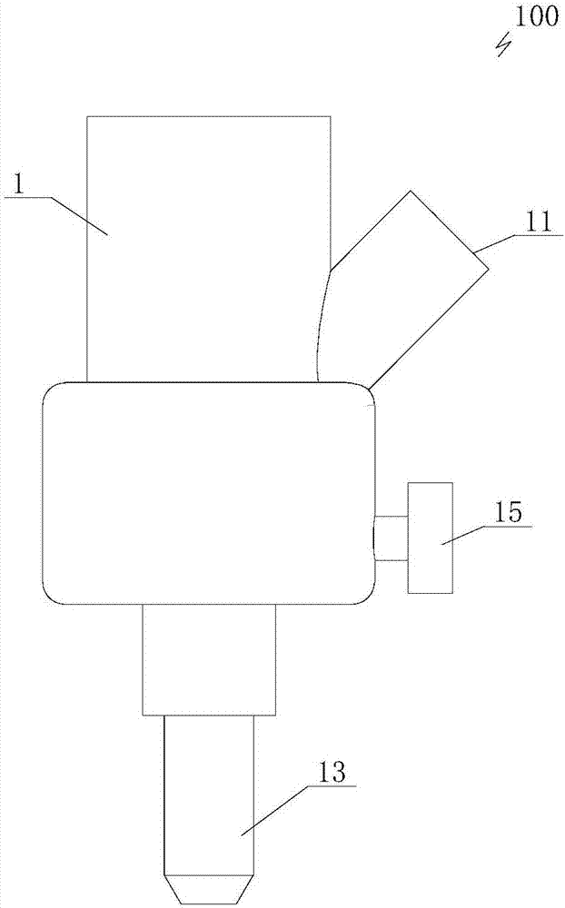
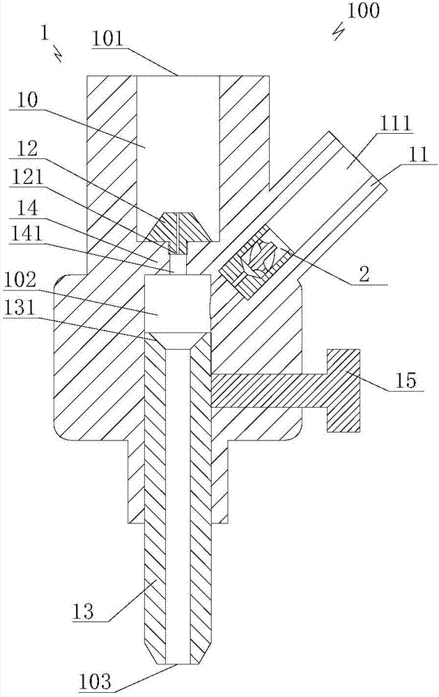
[0052] Embodiment 1, post-mixing generating device: as figure 1 , figure 2 As shown, the inner cavity 10 of the body is fixedly provided with a liquid nitrogen nozzle 12 above the outlet of the water channel 111, the bottom of the inner cavity 10 of the body is pierced with a sand mixing pipe 13 from the outside to the inside, and at least one tight fitting is pierced on the side wall of the body 1. Fasten the screw 15, one end of the fastening screw 15 is pushed against the side wall of the sand mixing pipe 13, the sand mixing pipe 13 is made of wear-resistant material, and the hardness is relatively high, so as to ensure that it can withstand the strong grinding ability of ice particles The fastening screw 15 plays the role of fixing the sand mixing pipe 13 to ensure that the sand mixing pipe 13 is centered so that the liquid nitrogen and ice particle jets are in the best position to prevent partial wear. The top of the inner chamber of the sand mixing pipe 13 communicates...

Embodiment 2

[0055] Embodiment two, pre-mixing type generating device: as image 3 , Figure 4 As shown, the reduced diameter of the lower portion of the body lumen 10 forms a jet flow hole 16 , and the bottom of the jet flow hole 16 forms a jet outlet 103 . In order to make the mixed abrasive flow smoothly, a second transition cone surface 161 whose diameter tapers downward is formed between the top of the jet flow hole 16 and the mixing chamber 102 .

[0056] When the generator 100 of this embodiment is used for jet flow, the liquid nitrogen pump injects pressurized liquid nitrogen fluid from the liquid nitrogen inlet 101, and at the same time, the water pump injects water jets from the side interface 11, and the water jets form a very small atomizing nozzle 2. The atomized water droplets are mixed with the liquid nitrogen fluid inside the mixing chamber 102, and the atomized water droplets condense into solid ice particles in a very short time after contacting the liquid nitrogen fluid...


PUM


Abstract

The invention provides a liquid nitrogen and ice particle abrasive material jet method and a generating device of the liquid nitrogen and ice particle abrasive material jet method. According to the liquid nitrogen and ice particle abrasive material jet method, liquid nitrogen fluid is poured into the generating device from the top, atomized water drops are poured into the generating device at the position below the top of the generating device through an atomization spray nozzle at the same time, the atomized water drops make contact with the liquid nitrogen fluid to form ice particles, after the ice particles and the liquid nitrogen fluid are mixed in the generating device, the mixed ice particles and liquid nitrogen fluid are jetted and flow out from a bottom outlet of the generating device to form liquid nitrogen and ice particle jet flow, and the liquid nitrogen and ice particle jet flow conducts jet flow operation on a treatment object. The liquid nitrogen and ice particle abrasive material jet method and the generating device of the liquid nitrogen and ice particle abrasive material jet method can achieve free control over the concentration of abrasive materials and are high in operation efficiency, clean and free of pollution.

Description

technical field [0001] The invention relates to the technical field of abrasive jets, in particular to a liquid nitrogen and ice particle abrasive jet method and a generating device thereof. Background technique [0002] Abrasive water jet is a new processing technology developed on the basis of pure water jet processing. Abrasive water jet has the characteristics of high-pressure water jet, such as no wear, no dust, and cold processing. At the same time, its impact force and grinding force are much larger than high-pressure water jet. The system has low working pressure and high working efficiency. Therefore, abrasive jets are widely used in cleaning, cutting, rock breaking, machining, casing window opening and other fields. However, the current abrasive jets often have difficulties in adding abrasives and controlling the concentration, especially in large-scale applications in the field of oil and gas wells; in addition, the post-processing of abrasives during ground cutt...

Claims


Application Information

Patent Timeline
Patent Type & Authority Applications(China)
IPC IPC(8): B24C7/00
CPCB24C7/0007
Inventor 李敬彬黄中伟张广清李根生田守嶒代献伟
Owner CHINA UNIV OF PETROLEUM (BEIJING)
Why Eureka
Try Eureka