
Oily waste water treatment system

A waste water treatment system and waste water technology, applied in the direction of water/sewage multi-stage treatment, water/sludge/sewage treatment, filtration treatment, etc., can solve the problems of large use limitations, reduced oil scraping effect, and no sterilization function. Achieve the effect of improving the treatment effect and facilitating the circulation and cleaning

Inactive Publication Date: 2017-10-24
惠天昱
View PDF0 Cites 4 Cited by
  • Summary
  • Abstract
  • Description
  • Claims
  • Application Information

AI Technical Summary

Problems solved by technology

[0003] In the prior art, there are still many deficiencies in the oily wastewater treatment device. It has no sewage circulation mechanism, which causes the oil in the sewage to be cleaned incompletely; after the existing oily wastewater treatment device is used for a long time, the tension of the transmission belt Smaller, it is easy to cause a large gap between the scraper and the transmission belt, which reduces the effect of oil scraping; at the same time, the existing oily wastewater treatment device has no bactericidal function, resulting in fermentation in the treatment of edible oil, which has limitations in use Large, so there is an urgent need for an oily wastewater treatment system to solve the above problems

Method used


Image

  • Oily waste water treatment system
  • Oily waste water treatment system
  • Oily waste water treatment system

Examples


Embodiment Construction

[0024] In order to make the technical means, creative features, goals and effects achieved by the present invention easy to understand, the present invention will be further described below in conjunction with specific embodiments.

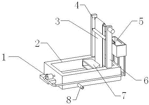
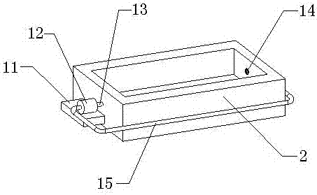
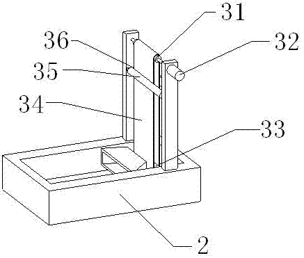
[0025] see Figure 1-Figure 4 , the present invention provides a technical solution: an oily wastewater treatment system, including a device main body, a wastewater stirring mechanism 1, a tension self-adaptive mechanism 3 and an oil scraping anti-fermentation mechanism 5, the device main body includes a sewage pool 2, a vertical plate 4, Riser 2 6, oil collection cover 7 and drain port 8, oil collection cover 7 is assembled inside the sewage pool 2, the lower end of vertical plate 1 4 is installed on the rear side of the upper end of the sewage pool 2, and the lower end of vertical plate 2 6 is installed in the sewage pool 2 On the front side of the upper end, the drain port 8 is assembled on the front end of the sewage tank 2 .

[0026] The was...


PUM


Abstract

The present invention provides an oily wastewater treatment system, which comprises a round roller 1, a motor, a round roller 2, a transmission belt, a fixed plate 1, an oil scraper, a fixed plate 2 and a collection box. The rear end of the round roller 1 is assembled on the The upper position of the front end surface of the vertical plate, the motor is installed at the upper position of the front end surface of the second vertical plate, and the first round roller is connected with the second round roller through a transmission belt. This design realizes the purpose of automatically adjusting the tension of the conveyor belt in the present invention. The collection box is arranged on the lower side of the oil scraper, the first fixed plate is installed on the right end surface of the vertical plate one, the second fixed plate is installed on the right end surface of the vertical plate two, the rear side of the lower end surface of the oil scraper is connected with the fixed plate The upper surface of the first end fits together, and the front side of the lower end of the oil scraper is attached to the upper end face of the second fixed plate. This design increases the sterilization function of the present invention. The present invention has high working efficiency, small footprint, low failure rate, and high stability. Well, high reliability.

Description

technical field [0001] The invention relates to an oily wastewater treatment system, which belongs to the field of sewage treatment equipment. Background technique [0002] With the rapid development of industry, a large amount of industrial wastewater generated in industrial production is discharged, and the pollution of water bodies is becoming more and more extensive and serious, threatening human health and safety. For the protection of the environment, the treatment of industrial wastewater is more important than the treatment of urban sewage. Among them, oily wastewater accounts for a large proportion of industrial wastewater, and oily wastewater will be generated in industrial operations in petroleum, petrochemical, steel, coking, gas generation stations, mechanical processing and other industries. If oily wastewater is not recycled, it will be wasteful; if it is discharged into rivers, lakes or bays, it will pollute the water body and affect the survival of aquatic ...

Claims


Application Information

Patent Timeline
IPC IPC(8): C02F1/40C02F9/02B01D17/022A61L2/10
CPCC02F1/40A61L2/10B01D17/0202C02F1/001
Inventor 惠天昱
Owner 惠天昱
Learn More