A pipeline robot for detection and cleaning of boiler headers in power plants

A technology for pipeline robots and power station boilers, which is applied to pipe components, special pipes, mechanical equipment, etc., can solve the problems that the detection device cannot meet the cleanliness inspection, there is no boiler header foreign matter removal device, and there are few pipeline cleaning robots. Good barrier performance, simple structure, and the effect of reducing size

Inactive Publication Date: 2020-01-17
XI AN JIAOTONG UNIV
View PDF9 Cites 0 Cited by
  • Summary
  • Abstract
  • Description
  • Claims
  • Application Information

AI Technical Summary

Problems solved by technology

For the inspection of the internal environment of the header, due to the narrow internal space of the header, there are welding seams, opening areas of the connection seat and machining residues, so the pipeline robot is required to be small enough and have good obstacle-surpassing performance, while the traditional The obstacle surmounting performance of the wheeled pipeline robot cannot meet the requirements. Although the obstacle surmounting performance of the traditional tracked pipeline robot is good, it is difficult to miniaturize the size, so the traditional detection device cannot meet the requirements of cleanliness inspection.
[0005] For the above problems in the traditional operation mode, there is currently no removal device for foreign matter in the boiler header. The current pipeline robots are mostly pipeline inspection robots, and there are few pipeline cleaning robots, and they are generally developed for specific pipelines, which are more versatile. Therefore, it is urgent to develop a small intelligent robot suitable for boiler header cleanliness inspection and cleaning

Method used


Image

  • A pipeline robot for detection and cleaning of boiler headers in power plants
  • A pipeline robot for detection and cleaning of boiler headers in power plants
  • A pipeline robot for detection and cleaning of boiler headers in power plants

Examples


Embodiment Construction

[0027] The present invention will be further described in detail below in conjunction with the accompanying drawings.

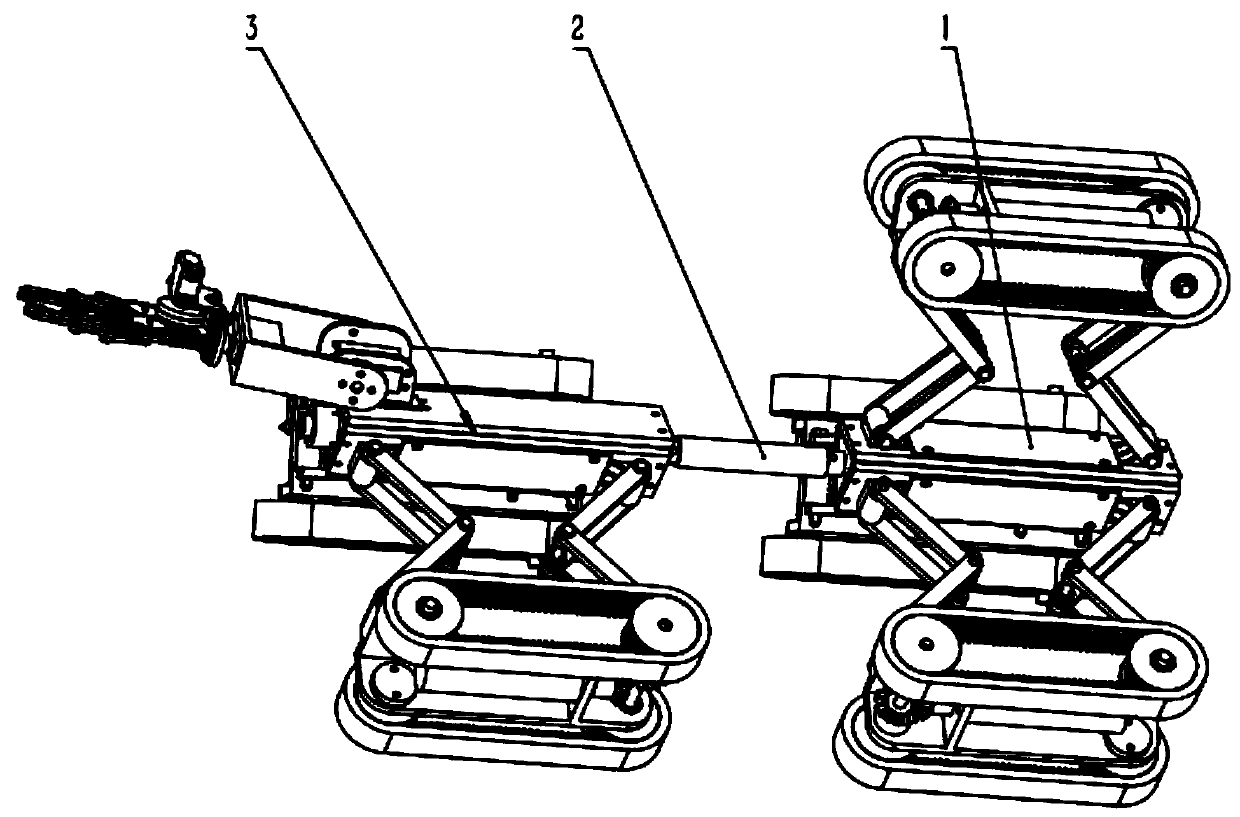
[0028] see figure 1 , the pipeline robot of the present invention includes a walking module 1 , a universal joint 2 and a cleaning module 3 , and the walking module 1 and the cleaning module 3 are connected through the universal joint 2 . Specifically, the pipeline robot is provided with an extension shaft on the side corresponding to the walking module 1 and the cleaning module 3, respectively, and the two ends of the universal joint 2 are respectively fixed on the extension shaft. When the pipeline robot used for the detection and cleaning of the boiler header of the power station passes through the bend, the universal joint 2 plays the role of a flexible connection.

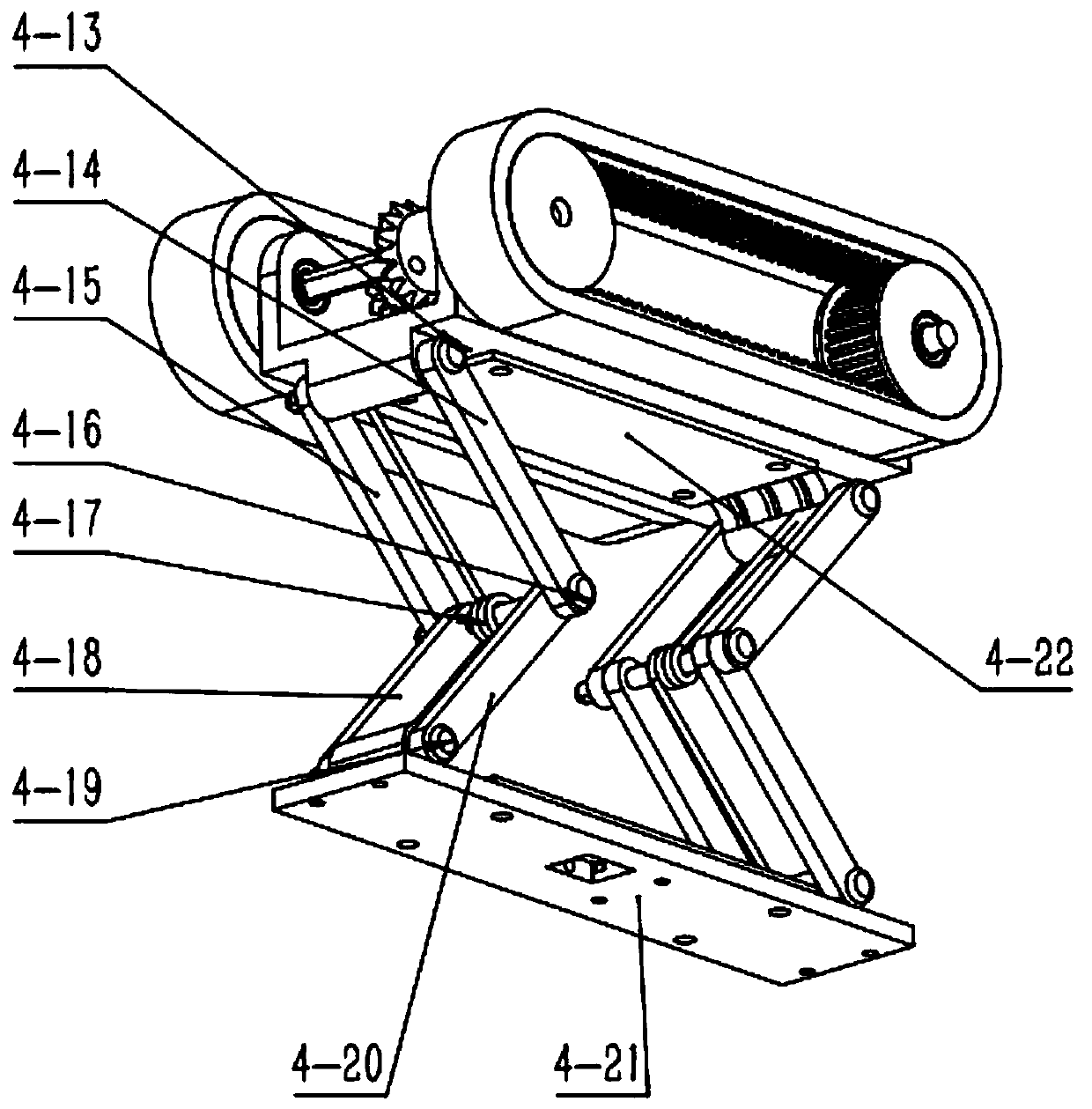
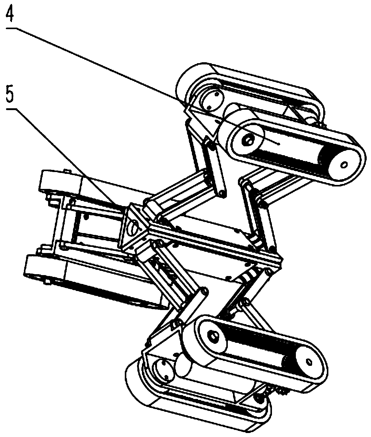
[0029] see figure 2 , the walking module 1 of the pipeline robot of the present invention has three groups of first walking units 4, and the three groups of walking units are evenly distri...


PUM


Abstract

A pipeline robot for detection and cleaning of a power station boiler header comprises a traveling module and a cleaning module, and the traveling module is connected with the cleaning module through a universal joint. The traveling module comprises a plurality of sets of first traveling units connected together. The first traveling units are evenly distributed in the radial direction of a robot spindle at intervals. The cleaning module comprises a plurality of sets of second traveling units and cleaning units connected together. The second traveling units and the cleaning units are evenly distributed in the radial direction of the robot spindle at intervals. The cleaning module further comprises a camera arranged at the front end of the robot spindle in the movement direction. The first traveling units and the second traveling units each comprise a traveling mechanism and a torsional connecting rod for supporting the traveling mechanism. Each cleaning unit comprises a mechanical paw and a plurality of steering engines for controlling omnibearing motion of the mechanical paw through a fixing support. The robot is small in size and good in obstacle crossing capacity and can adapt to pipelines of different pipe diameters, and the pipe diameter adjustment range is wide.

Description

technical field [0001] The invention relates to the field of boiler pipeline cleaning, in particular to a pipeline robot used for detection and cleaning of boiler headers in power plants. Background technique [0002] The boilers of supercritical and ultra-supercritical units achieve the purpose of balancing the characteristics of steam and water and the flow rate of working medium by adding orifice rings inside the header or heating surface pipes. The cleaning requirements inside the boiler are high. Due to the extremely short operation time of the boiler, in addition to excluding factors such as the quality of the pipe material and the operation of superparameters, it is determined that the cause of the pipe burst is the blockage of mechanical processing residues in the throttling hole in the header or the heating surface pipe, which causes heat exposure. Short-term over-temperature tube burst. The occurrence of pipe burst accidents will cause unplanned start and stop of ...

Claims


Application Information

Patent Timeline
Patent Type & Authority Patents(China)
IPC IPC(8): F16L55/32F16L55/40F16L101/12F16L101/30
CPCF16L55/32F16L55/40F16L2101/12F16L2101/30
Inventor 王孙安刘洋朱瑞祺孙丁蔡稳牢
Owner XI AN JIAOTONG UNIV
Why Eureka
Try Eureka