Refrigerant flow control method of water chilling unit

A technology for a chiller and a control method, which is applied to refrigerators, refrigeration components, refrigeration and liquefaction, etc., can solve problems such as low performance, and achieve the effect of improving load heat transfer efficiency and reducing the risk of liquid carrying

Active Publication Date: 2017-10-24
MCQUAY AIR CONDITIONING & REFRIGERATION WUHAN
View PDF11 Cites 6 Cited by
  • Summary
  • Abstract
  • Description
  • Claims
  • Application Information

AI Technical Summary

Problems solved by technology

[0004] The technical problem to be solved by the present invention is to provide a method for controlling the refrigerant flow rate of a water chiller, solve the problem of low performance under partial load under traditional liquid level control, and improve the heat exchange efficiency of the evaporator

Method used


Image

  • Refrigerant flow control method of water chilling unit
  • Refrigerant flow control method of water chilling unit

Examples


Embodiment Construction

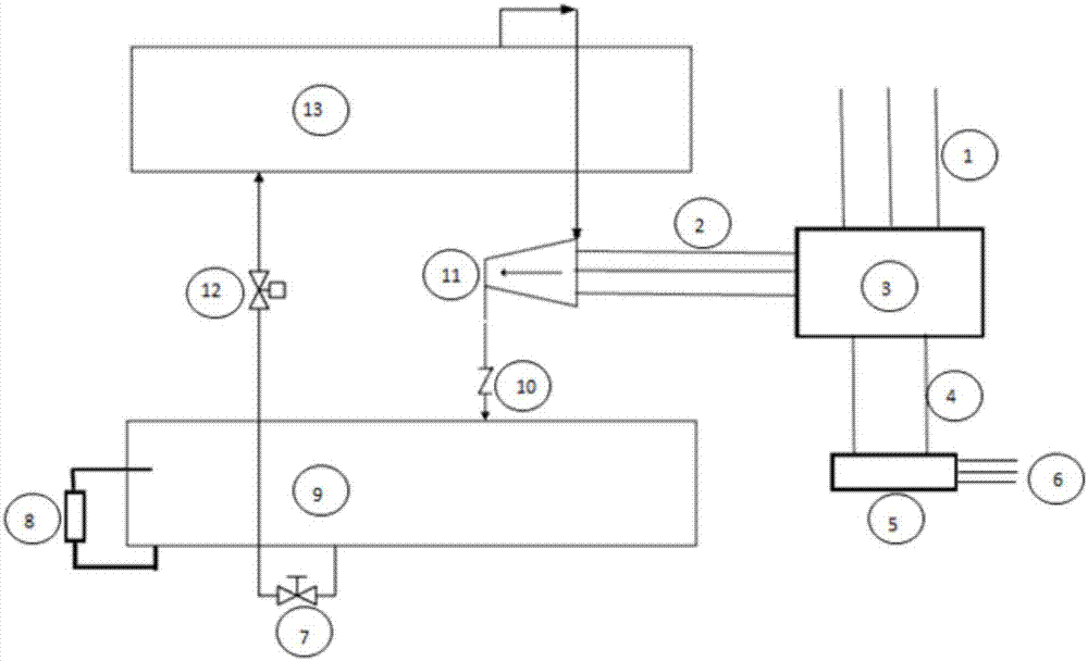
[0034] The structure of the chiller system used in the chiller refrigerant flow control method implemented according to the present invention is as follows: figure 1 As shown, it mainly includes a condenser 9, an evaporator 13, a compressor 11, and a micro-control cabinet 5 equipped with a controller. , the compressor 11 is connected to the evaporator 13, and the compressor 11 is connected to the condenser 9 through the exhaust check valve 10; Connection, the starter cabinet 3 is connected to the signal of the micro-control cabinet 5 through the communication line 4 between the starter cabinet and the micro-control cabinet, and the micro-control cabinet 5 is connected to each sensor and valve control element through the communication line 6 between the micro-control cabinet and the electrical parts of the unit signal connection. The main throttling device is the electronic expansion valve 12 .

[0035]It is not shown in the figure but those skilled in the art should be clear...


PUM


Abstract

The invention discloses a refrigerant flow control method of a water chilling unit. In the operating process of the water chilling unit, a controller calculates the RLA (Rated Load Amperes) in real time; meanwhile, according to a present state of the unit, a corresponding volume flow is determined according to a corresponding map relation between the working conditions of a compressor and a volume flow of a main throttling device; then, a corresponding target liquid level section is determined according to the RLA and the volume flow; and finally, the controller applies a PID control method to automatically adjust a liquid level target of a condenser according to the load change of the compressor, and the liquid level target of the condenser is controlled in a corresponding condenser target liquid level section so as to indirectly control a liquid level of an evaporator. The method solves the problem of low performance of part load under traditional liquid level control, improves the defect of incapability of stably controlling the liquid level of the evaporator, and improves the heat exchange efficiency of the evaporator.

Description

technical field [0001] The invention relates to the technical field of refrigeration and heat exchange, in particular to a method for controlling the refrigerant flow rate of a chiller. Background technique [0002] With the release of the energy-saving product standard GB19577 for chillers and the introduction of the concept of comprehensive performance evaluation, more and more attention has been paid to partial load efficiency. The energy-saving index is also changed from full load evaluation to comprehensive load performance evaluation. [0003] The traditional refrigerant flow control method uses a condenser liquid level sensor (or evaporator liquid level sensor) combined with an electronic expansion valve EXV plus a controller as the hardware basis to fix the liquid level target of the condenser (that is, in the prior art In liquid level control, the target liquid level is always constant), and the fixed liquid level target is achieved by PID regulating the electronic...

Claims


Application Information

Patent Timeline
Patent Type & Authority Applications(China)
IPC IPC(8): F25B39/04
CPCF25B39/04F25B2600/02
Inventor 王达彭林张思秀
Owner MCQUAY AIR CONDITIONING & REFRIGERATION WUHAN
Why Eureka
Try Eureka