
Compact type cross beam type hydraulic pusher

A pusher and compact technology, applied in the field of compact beam-type hydraulic pushers, can solve the problems of large floor space, wear, and shorten the service life of hydraulic cylinders, and achieve a small footprint, compact structure, and energy saving. cost effect

Pending Publication Date: 2017-10-24
中重科技(天津)股份有限公司
View PDF4 Cites 5 Cited by
  • Summary
  • Abstract
  • Description
  • Claims
  • Application Information

AI Technical Summary

Problems solved by technology

[0006] (1) Two sets of independent hydraulic cylinder propulsion devices cannot achieve synchronization, and it is prone to the phenomenon that one group of hydraulic cylinders moves fast and one group of hydraulic cylinders moves slowly
Because it is out of sync, every time it is pushed, it will twist and move forward in the furnace, which will aggravate the wear of the slideway in the furnace and cause jamming.
[0007] (2) The stroke of the hydraulic cylinder is long, and the guide rod is a slender rod, which is used to bear the gravity of the beam and the push head. When the billets are pushed side by side, they will bulge upward, which will increase the additional radial load of the guide post and cause bending deformation. , the piston rod of the hydraulic cylinder will also bend and deform, reducing the service life of the hydraulic cylinder
[0008] (3) During the retraction process of the hydraulic cylinder, the beam and the push head are heavy, and the sliding bearing is used in the guide rod. The long-term wear is serious, and the sinking phenomenon occurs. The bending of the piston rod of the hydraulic cylinder will also affect the service life of the hydraulic cylinder.
[0009] (4) Large footprint and heavy equipment weight

Method used


Image

  • Compact type cross beam type hydraulic pusher
  • Compact type cross beam type hydraulic pusher
  • Compact type cross beam type hydraulic pusher

Examples


Embodiment Construction

[0039] It should be noted that, in the case of no conflict, the embodiments of the present invention and the features in the embodiments can be combined with each other.

[0040] In describing the present invention, it should be understood that the terms "center", "longitudinal", "transverse", "upper", "lower", "front", "rear", "left", "right", " The orientations or positional relationships indicated by "vertical", "horizontal", "top", "bottom", "inner" and "outer" are based on the orientations or positional relationships shown in the drawings, and are only for the convenience of describing the present invention and Simplified descriptions, rather than indicating or implying that the device or element referred to must have a particular orientation, be constructed and operate in a particular orientation, and thus should not be construed as limiting the invention. In addition, the terms "first", "second", etc. are used for descriptive purposes only, and should not be understood ...


PUM


Abstract

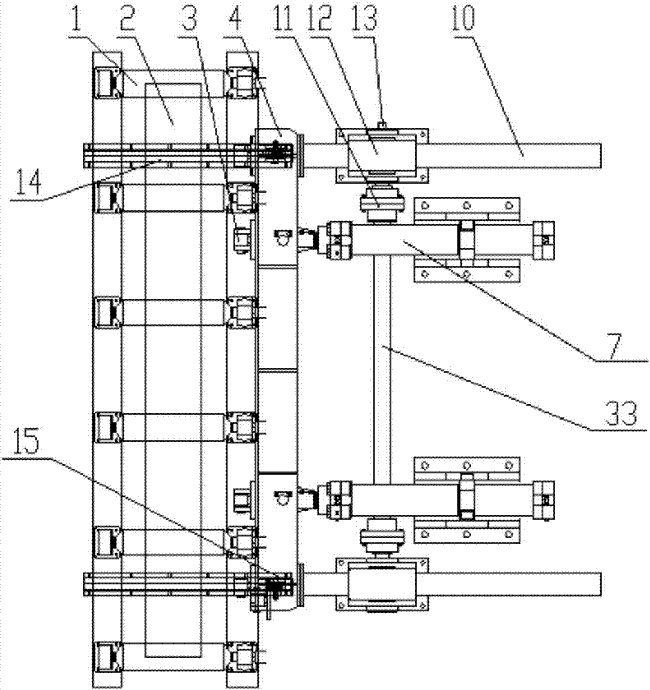
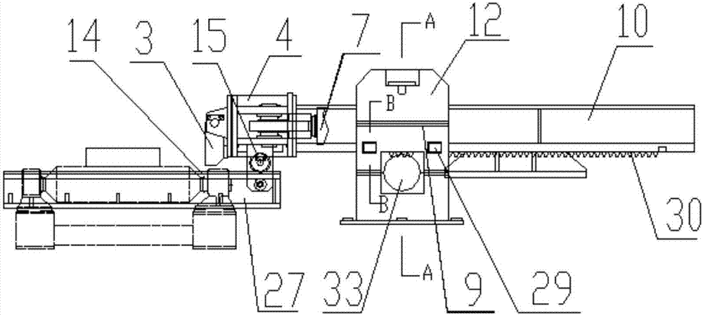
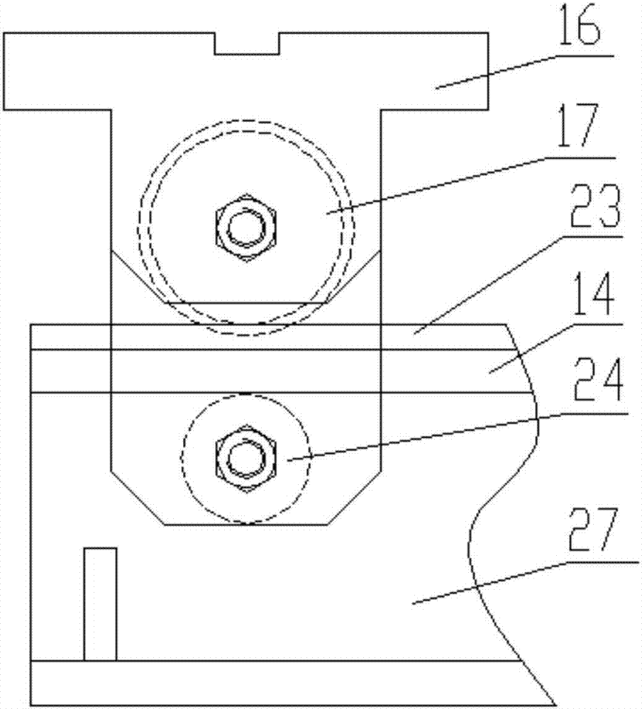
The invention provides a compact type cross beam type hydraulic pusher which comprises a push head, a cross beam, guide rail beams, fixed wheel groups, mechanical synchronizing devices and hydraulic cylinders. The fixed wheel groups are clamped and fixed to the guide rail beams through double-rim wheels and hook wheels, so that the fixed wheel groups can but make linear motion in the direction of the guide rail beam. Each mechanical synchronizing device comprises a rack guide rod, a gear box and a coupler; each rack guide rod is clamped in the middle position by an upper pressing wheel, lower supporting wheels and pressing wheels on the left side and the right side in one corresponding gear box, and thus can but make linear motion through the limitation of a gear between the corresponding lower supporting rollers; the gear in each box body is connected with a synchronizing shaft depending on a key; the ends of the synchronizing shafts in the two box bodies are connected with the couplers correspondingly; and mechanical synchronization of the two rack guide rods is realized. The compact type cross beam type hydraulic pusher is compact in structure, small in floor area and light in weight, the mechanical property of an existing pusher is not changed, the compact type cross beam type hydraulic pusher is simple in structure and convenient to mount and maintain, and is more stable and reliable, the mechanical synchronization is realized, and thus the production efficiency is improved.

Description

technical field [0001] The invention belongs to the field of metallurgical steel rolling machinery equipment, in particular to a compact beam type hydraulic steel pushing machine. Background technique [0002] The production level of steel is an important symbol to measure the modernization level of a country. my country's iron and steel has developed rapidly. Hot-rolled strip steel and section steel have always occupied an important proportion of steel production. They are widely used in civil, industrial, bridge, petroleum, construction, subway and other fields, showing excellent mechanical properties. With the rapid development of the economy, the demand for product output is increasing day by day, the product quality is more high-precision, and the requirements for production equipment are higher. However, it is also necessary to improve the performance of auxiliary equipment. Therefore, strengthening the structural stability and synchronization of the pusher is to be so...

Claims


Application Information

Patent Timeline
IPC IPC(8): F27D3/04
CPCF27D3/04
Inventor 薛念辉
Owner 中重科技(天津)股份有限公司
Learn More