Overhead transmission line laying device for agricultural power transmission

A technology for laying devices and overhead lines, applied in the direction of overhead lines/cable equipment, etc., can solve the problems of consuming physical strength, reducing the efficiency of overhead lines, and slow construction progress.

Inactive Publication Date: 2017-10-24
STATE GRID SHANDONG ELECTRIC POWER COMPANY WEIFANG POWER SUPPLY +1
View PDF0 Cites 0 Cited by
  • Summary
  • Abstract
  • Description
  • Claims
  • Application Information

AI Technical Summary

Problems solved by technology

Therefore, after the wire tightening work is over, the staff has to use their shoulders to lift the wires out of the trolley, lift them up to the height of the insulator, and put them into the groove on the top of the insulator for binding. This requires a lot of physical strength and seriously affects the work. schedule
[0004] In the construction, the conductors with small diameters are relatively light, and the staff can complete the lifting and binding of the conductors without much effort. For the phase line, since the pay-off block must also be fixed on the lower cross arm, the distance from the insulator on the top of the pole is about 1100mm. The height distance is very large, and sometimes even two people are required to complete it, which will easily lead to slow construction progress and delay in power transmission time. status
The second disadvantage is that in order to reduce the difficulty of lifting the neutral phase line, the pay-off block is usually removed from the lower cross arm, and then fixed to the top cap of the neutral phase line for use. The problem caused by this is that it needs a second It is very inconvenient to disassemble and install the wire block
The third disadvantage is that after the wire is lifted to a higher insulator, the tension of ...

Method used


Image

  • Overhead transmission line laying device for agricultural power transmission
  • Overhead transmission line laying device for agricultural power transmission
  • Overhead transmission line laying device for agricultural power transmission

Examples


Embodiment Construction

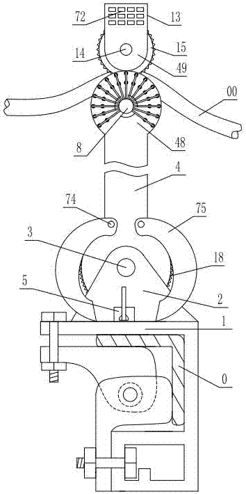
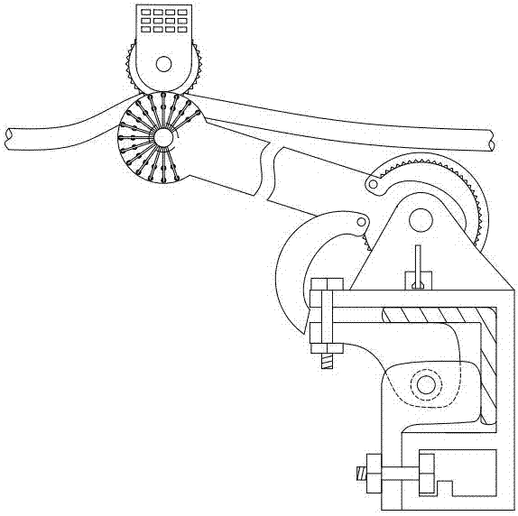
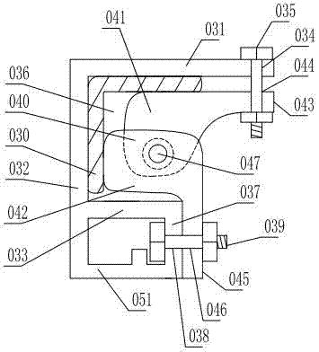
[0036] As shown in the figure, the agricultural power transmission overhead line laying device includes a base 1, and the bottom of the base is provided with a lower locking device that is locked and matched with the cross arm 0 of the pole. The extended upper plate 031, the rear end of the upper plate 031 is vertically fixed with a vertical plate 032 extending downward, the lower part of the longitudinal plate 032 is fixed with a lower plate 033 arranged in parallel with the upper plate 031, and the end of the upper plate 031 is provided with The upper hole 034, the upper connecting bolt 035 is inserted in the upper hole 034, the clamping groove 036 for accommodating the cross arm 0 is formed between the upper plate 031 and the lower plate 033, and the end of the lower plate 033 is fixed with a vertically extending lower plate 033. The extension plate 037, the extension hole 038 is set on the extension plate 037, the extension bolt 039 is inserted in the extension hole 038, an...


PUM


Abstract

The invention discloses an overhead line laying device for agricultural power transmission, which comprises a base, the bottom of which is provided with a lower locking device for locking and cooperating with the pole cross-arm, the base is fixed with a bracket, and the bracket is hinged with a support tube through the bracket shaft , the bracket is provided with a lower positioning device for positioning and matching the support cylinder, the upper end of the support cylinder is installed with an upper gear that rotates close to the outer surface of the main support plate through a rotating connection device, and the support cylinder is equipped with a gear that is snapped and positioned with the teeth of the upper gear In the upper positioning device, an upper bracket is hinged on the upper part of the upper gear, and an upper locking device is arranged between the auxiliary support plate and the upper bracket. The advantage is that it is easy to install, reliable to fix, and easy to disassemble. It can freely adjust the pay-off height according to the actual height of the pole insulator, and can automatically determine the length of the pay-off cable. It only needs to be installed and disassembled once when the wire is set up. After the wire tightening operation, it only needs to translate the wire. Yes, the tightness of the wires before and after the tightening is consistent to ensure the quality, and one person can operate it.

Description

technical field [0001] The invention relates to a laying device for agricultural power transmission overhead lines. Background technique [0002] The pay-off pulley is a tool that must be used in the construction of power lines. The main structure is composed of aluminum or nylon pulleys, frame fixing devices, hooks or U-shaped groove stabilization devices. The use of pulleys in the process of line erection and tightening can reduce the wire The friction resistance can prevent the strand damage of the wire and the damage of the insulation layer, and can improve the construction speed and reduce the power outage time. [0003] Now in the construction of power lines of 10kV and below, the pay-off pulley used is about 140mm from the U-shaped groove stabilization device to the top of the pulley, while the height of the P-15 rod insulator is about 240mm, and the P-20 rod insulator height is about 240mm. The height of the insulator is about 350mm, the pulley is short, the insulat...

Claims


Application Information

Patent Timeline
IPC IPC(8): H02G1/04
CPCH02G1/04
Inventor 徐业堂李玉亮李国华孙瑞玲王立勇王娟娟辛庆国曲万红赵玉京范蓁蓁孟庆江李广跃陈洪正孙红卫徐志富
Owner STATE GRID SHANDONG ELECTRIC POWER COMPANY WEIFANG POWER SUPPLY
Why Eureka
Try Eureka