
Automatic loading and collecting mechanism for precision numerical-control machine tool

A technology of precise numerical control and collection mechanism, which is applied in the field of numerical control machine tools, can solve the problems of low material placement efficiency of workers, limited workpiece capacity, and high use value, and achieves the effect of facilitating inspection of workpiece quality, avoiding workpiece collision, and high use value.

Pending Publication Date: 2017-10-27
SHAANXI HALET PRECISION MACHINERY
View PDF9 Cites 6 Cited by
  • Summary
  • Abstract
  • Description
  • Claims
  • Application Information

AI Technical Summary

Problems solved by technology

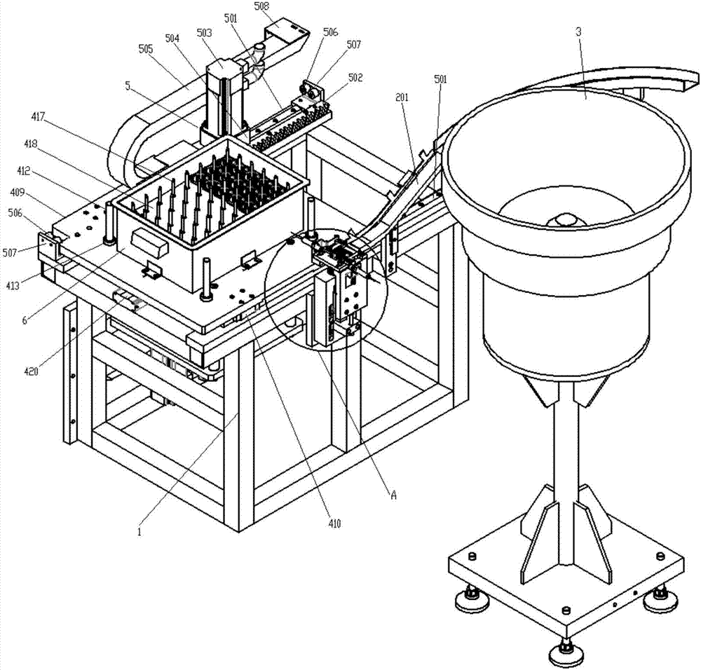
[0003] The technical problem solved by the present invention is to provide an automatic feeding and collecting mechanism used in precision numerical control machine tools, through which the materials in the vibrating plate are automatically sent into the grabbing area through the feeding mechanism on the base bracket and then positioned, improving the To improve the feeding efficiency, after the jacking mechanism and the positioning mechanism work together, the problems of low efficiency, high strength and limited workpiece capacity of workers are effectively solved, so that the workpieces are neatly collected into the turnover box according to the processing sequence, which is convenient for collection Inspect the quality of the workpiece in the process, with high use value

Method used


Image

  • Automatic loading and collecting mechanism for precision numerical-control machine tool
  • Automatic loading and collecting mechanism for precision numerical-control machine tool
  • Automatic loading and collecting mechanism for precision numerical-control machine tool

Examples


Embodiment Construction

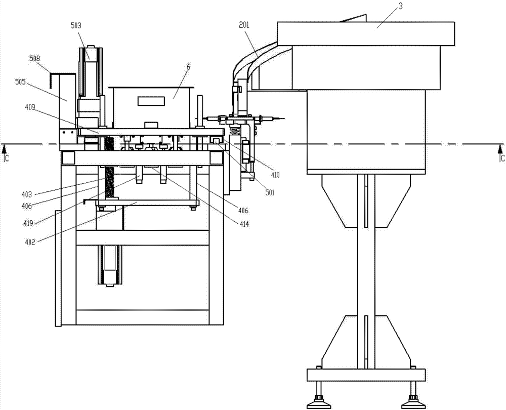
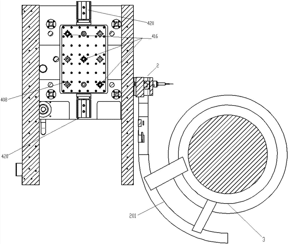
[0019] Attached below Figure 1-6 An embodiment of the present invention is described.

[0020]The automatic feeding and collecting mechanism used in precision numerical control machine tools has a base bracket 1, and the upper right end of the base bracket 1 is provided with a feeding device 2, and the upper end of the feeding device 2 is connected to a vibrating plate 3 located outside the right side of the base bracket 1 The upper end is fixedly connected, and the materials in the vibrating plate 3 are transported to the grabbing area through the feeding device 2 and positioned, and then the materials on the feeding device 2 are grabbed by the manipulator to the precision numerical control machine tool to realize the feeding of the materials. The middle part of the base support 1 is provided with a jacking mechanism 4 and the upper end surface of the jacking mechanism 4 is fixed with a turnover box 6. After the positioning mechanism 5 cooperates to realize the automatic co...


PUM


Abstract

The invention provides an automatic loading and collecting mechanism for a precision numerical-control machine tool. The automatic loading and collecting mechanism is characterized in that a loading device is arranged at the right upper end of a base support, the upper end of the loading device is fixedly connected with the upper end of a vibrating plate positioned on the outside of the right side of the base support, materials in the vibrating plate can be conveyed to grabbing zones by the loading device and are grabbed onto the precision numerical-control machine tool by manipulators after being positioned, a jacking mechanism is arranged in the middle of the base support, a turnover tank is fixed to the upper end surface of the jacking mechanism, a repositioning mechanism which is connected with the jacking mechanism is arranged at the upper end of the base support, and workpieces can be automatically collected into the turnover tank after cooperative work is carried out by the jacking mechanism and the repositioning mechanism. The automatic loading and collecting mechanism has the advantages that the materials in the vibrating plate can be automatically conveyed into the grabbing zones by a loading mechanism on the base support and then can be positioned, and accordingly the loading efficiency can be improved; the problems of low arrangement efficiency of workers, high intensity and workpiece capacity limitation can be effectively solved after cooperative work is carried out by the jacking mechanism and the repositioning mechanism, and the automatic loading and collecting mechanism can bring convenience for inspecting the quality of the workpieces in collecting procedures and has high service value.

Description

technical field [0001] The invention belongs to the technical field of numerical control machine tools, and in particular relates to an automatic feeding and collecting mechanism used in precision numerical control machine tools. Background technique [0002] At present, the storage mechanism installed in domestic precision CNC machine tools must realize automatic control in the gripping area of ​​the manipulator. Due to the limited gripping area of ​​the manipulator, the storage mechanism mostly adopts a solid-type tray structure, and the use of a solid-type tray will inevitably limit the storage capacity of the workpiece. Therefore, the frequency of loading and unloading of workers is increased, continuous operation cannot be realized, and processing efficiency is reduced; in addition, the storage mechanism must be installed within the working range of the manipulator of the machine tool, that is, inside the machine tool. Due to the limited installation position, it is inco...

Claims


Application Information

Patent Timeline
IPC IPC(8): B23Q7/00
CPCB23Q7/00
Inventor 周文斌吴小刚
Owner SHAANXI HALET PRECISION MACHINERY
Learn More