Metal sound barrier for bridge

A sound barrier and metal technology, applied in the direction of construction, noise absorption devices, etc., can solve the problems of increasing product weight, low strength of glass fiber cotton, increasing production process, etc., to achieve overall weight reduction, good sound absorption effect, high The effect of structural strength

Inactive Publication Date: 2017-10-27
JIANGSU XINGUANG ENVIRONMENTAL PROTECTION ENG
View PDF6 Cites 5 Cited by
  • Summary
  • Abstract
  • Description
  • Claims
  • Application Information

AI Technical Summary

Problems solved by technology

The current metal sound barrier is mainly made of aluminum alloy as the external metal skeleton, and glass fiber cotton as the internal sound-absorbing material. Due to the low strength of glass fiber cotton, it is necessary to install calcium silicate board inside an

Method used


Image

  • Metal sound barrier for bridge
  • Metal sound barrier for bridge
  • Metal sound barrier for bridge

Examples


Embodiment 1

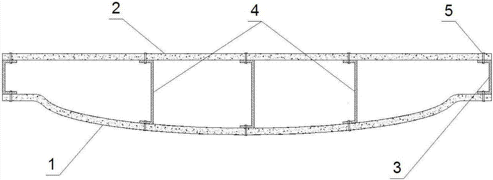
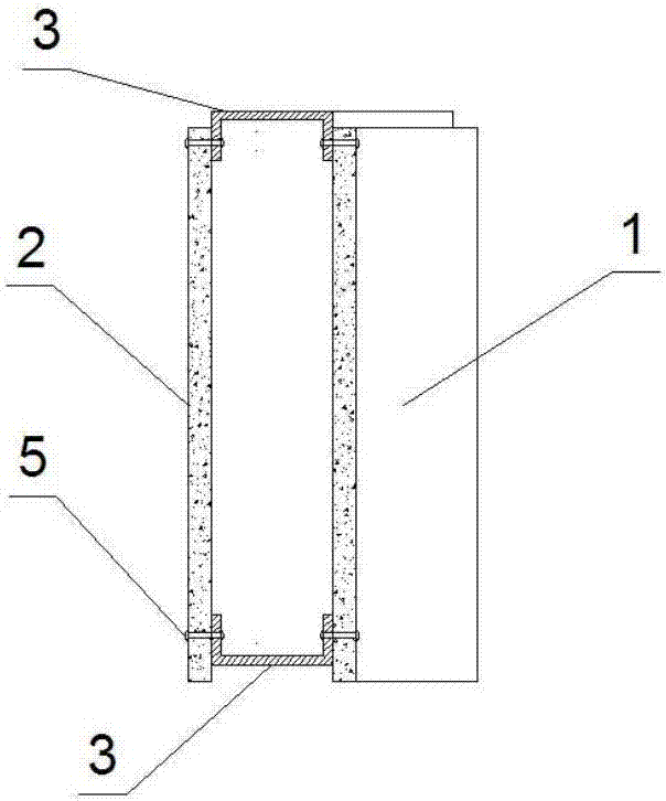
[0024] A metal sound barrier for a bridge, comprising a foamed aluminum panel 1, a backboard and galvanized steel sheets on four sides, the foamed aluminum panel 1 is micro-through-hole foamed aluminum, and the foamed aluminum backboard 2 is closed-cell foamed aluminum, The two ends of the foamed aluminum panel 1 are straight and the middle is an outwardly convex arc, the arc height is equal to the thickness of the sound barrier, the foamed aluminum backboard 2 is a flat plate, and the galvanized steel plate is pressed into a U-shaped section profiles, aluminum foam panels 1 and back panels and galvanized steel profiles 3 are fixedly connected with rivets 5 to form a metal sound barrier with a cavity structure, and the galvanized steel profiles 3 above the sound barrier slightly protrude from the panels and the back panel On the upper edge, the galvanized steel profile 3 below the sound barrier is slightly indented on the lower edge of the panel and the back panel, and three U-...

Embodiment 2

[0026] It is basically the same as Example 1, except that the foamed aluminum panel 1 is through-hole foamed aluminum, the foamed aluminum backboard 2 has the same shape as the panel and the arc protrudes in the same direction, and the cavity is filled with polyurethane foam material. The measured noise reduction coefficient of the product is 0.75, the weighted sound insulation is 35dB, the surface density is 25kg / m2, the bending fracture load is ≥7.0kPa, and the combustion performance is A1.

Embodiment 3

[0028] It is basically the same as Embodiment 2, except that the aluminum foam backboard 2 protrudes in the opposite direction to the arc of the panel, and the cavity is filled with glass fiber cotton. The measured noise reduction coefficient of the product is 0.77, the weighted sound insulation is 33dB, the surface density is 22kg / m2, the bending fracture load is ≥7.0kPa, and the combustion performance is A1.


PUM

PropertyMeasurementUnit
Areal densityaaaaaaaaaa

Abstract

The invention discloses a metal sound barrier for a bridge. The metal sound barrier comprises a foamed aluminum face plate, a foamed aluminum back plate and four galvanized steel plates on the side faces. The two ends of the foamed aluminum face plate are straight, and the middle of the foamed aluminum face plate is in an outward-protruding arc shape. The galvanized steel plates are compressed into sectional materials with the U-shaped sections. The foamed aluminum face plate, the foamed aluminum back plate and the galvanized steel plates are fixedly connected into the metal sound barrier with a cavity structure. The front face of the metal sound barrier is of an arc-shaped structure, so that the structural strength of the metal sound barrier is higher than that of a sound barrier with the same width; the metal sound barrier is provided with a hollow cavity, so that the overall weight is decreased; and the face plate and the back plate are made of foamed aluminum, so that the sound absorption effect is better, and the strength is guaranteed.

Description

technical field [0001] The invention belongs to the field of sound barriers, in particular to a bridge metal sound barrier. Background technique [0002] The sound barrier is a sound shielding structure with sufficient surface density located between the sound source and the sound receiving point. The limited length of the sound barrier built in the local areas on both sides of the sound source can make the operating noise of the sound source have a significant additional effect during the propagation process. Attenuation, so as to reduce the influence of noise in a certain area where the receiver is located, so as to improve the acoustic environment quality of the surrounding environment. Due to the characteristics of the structure and use of the bridge, there are certain requirements for the gravity of the auxiliary parts on it, and because some bridges did not consider the influence of the weight of the sound barrier at the beginning of the design, it is required that the...

Claims


Application Information

Patent Timeline
IPC IPC(8): E01F8/00
CPCE01F8/0029
Inventor 许晶晶高琍玲张玉岁洪少华宣君
Owner JIANGSU XINGUANG ENVIRONMENTAL PROTECTION ENG
Why Eureka
Try Eureka