Split cooling apparatus for internal combustion engine

A technology of separating cooling and internal combustion engine, applied in the direction of engine cooling, liquid cooling, measuring device, etc., can solve the problems of increasing size, complex structure of integrated valve, reducing cooling efficiency, etc., to achieve weight reduction, simple and reliable control, cost reduction effect

Active Publication Date: 2017-10-31
HYUNDAI MOTOR CO LTD +1
View PDF5 Cites 2 Cited by
  • Summary
  • Abstract
  • Description
  • Claims
  • Application Information

AI Technical Summary

Problems solved by technology

However, the former structure uses plastic casting, and due to the gap corresponding to the casting tolerance, the flow of cooling water is scattered, which reduces the cooling efficiency, while the latter structure requires additional separate cooling when applying an integral flow control valve valve, which complicates the structure of the one-piece valve and increases its size

Method used


Image

  • Split cooling apparatus for internal combustion engine
  • Split cooling apparatus for internal combustion engine
  • Split cooling apparatus for internal combustion engine

Examples


Embodiment Construction

[0030] The following description is merely exemplary in nature and is not intended to limit the disclosure, application and uses. It should be understood that throughout the drawings, corresponding reference numerals indicate like or corresponding parts and features.

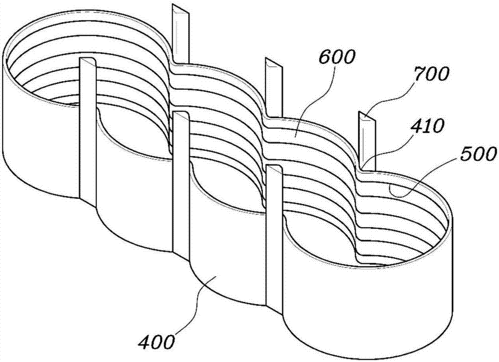
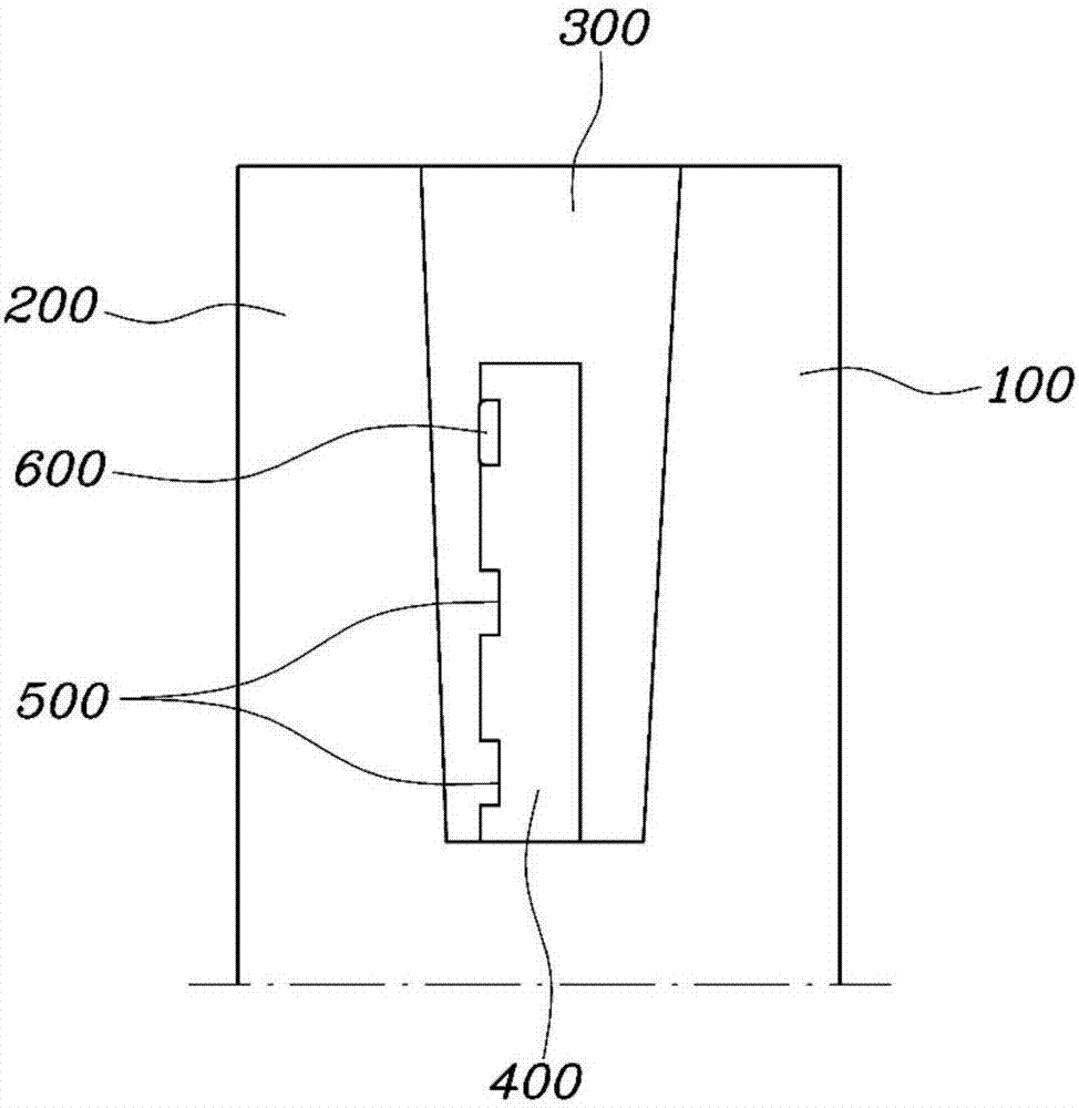
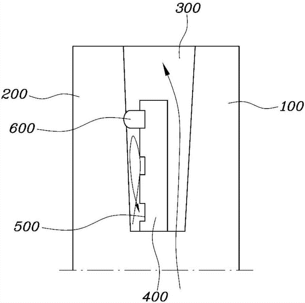
[0031] figure 1 is a perspective view showing a separate cooling device for an internal combustion engine according to one form of the present disclosure; figure 2 is equipped with a figure 1 A side sectional view of the cylinder block of the split cooling arrangement shown; image 3 With figure 2 A corresponding view, but showing the state of the cylinder block after expansion of the sealing member; and Figure 4 to Figure 6 is a side sectional view illustrating various forms of a separate cooling device for an internal combustion engine according to the present disclosure.

[0032] A separate cooling device for an internal combustion engine according to one form of the present disclosure includes: a bas...


PUM


Abstract

The present disclosure provides a split cooling apparatus for an internal combustion engine, the apparatus including: a base inserted into a water jacket of a cylinder block, the base surrounding an outside of a cylinder along a shape of the cylinder; an insertion groove formed on the base by being depressed into an inner surface of the base; and a sealing member inserted into the insertion groove, wherein when a temperature of cooling water supplied into the water jacket reaches a preset temperature or higher, the sealing member expands so as to close a flow passage between the base and the cylinder, thereby increasing flow resistance of the cooling water and thus reducing a heat transfer rate of the cylinder.

Description

technical field [0001] The present disclosure relates generally to a cooling arrangement for an internal combustion engine, and more particularly, to a separate cooling arrangement for an internal combustion engine. Background technique [0002] The statements in this section merely provide background information related to the present disclosure and may not constitute prior art. [0003] In general, conventional vehicles employ a siamese-type cylinder block in a multi-cylinder engine with a short distance between cylinders (bore pitch) for reducing The purpose of the size, weight and overall length of a multi-cylinder engine. Since the one-piece cylinder block has no water jacket (cooling water passage) between the cylinder liners and it is formed by casting a plurality of cylinder liners using aluminum in order to join them to each other, the one-piece cylinder block is configured as a cylinder core Short distance. [0004] Since the one-piece cylinder block has a short...

Claims


Application Information

Patent Timeline
Patent Type & Authority Applications(China)
IPC IPC(8): F01P3/02F01P7/16F01P11/00
CPCF01P3/02F01P7/16F01P11/00F01P2025/08F01P2003/028F01P2003/027F01P2003/021F02F1/14
Inventor 梁光植张珉硕朴焌植李宇庸
Owner HYUNDAI MOTOR CO LTD
Why Eureka
Try Eureka