
Ultrasonic endoscope and signal transmission device thereof

A signal transmission and endoscope technology, applied in the field of medical equipment, can solve problems such as brush impedance instability, image quality deterioration, brush slip ring wear, etc., to achieve fast rotation speed, extended life, and low processing Effect

Pending Publication Date: 2017-11-03
INNERMEDICAL CO LTD
View PDF5 Cites 0 Cited by
  • Summary
  • Abstract
  • Description
  • Claims
  • Application Information

AI Technical Summary

Problems solved by technology

However, the brush slip ring wears seriously under long-term high-speed rotation conditions, and its service life is short; at the same time, because the brush impedance is not constant during the rotation process, it is easy to generate interference signals and deteriorate the image quality

Method used


Image

  • Ultrasonic endoscope and signal transmission device thereof
  • Ultrasonic endoscope and signal transmission device thereof
  • Ultrasonic endoscope and signal transmission device thereof

Examples


Embodiment 1

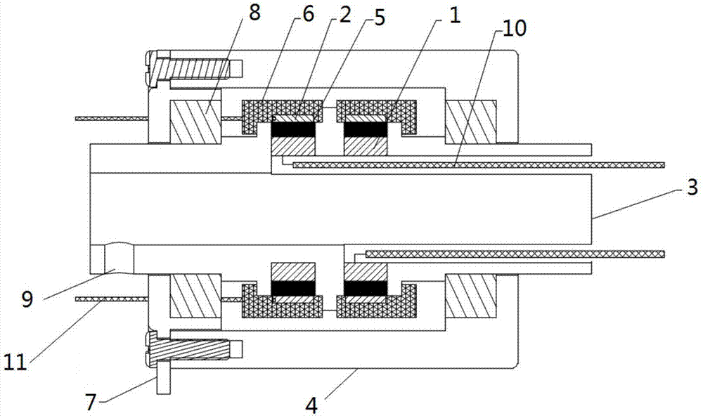
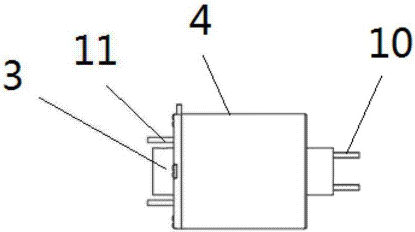
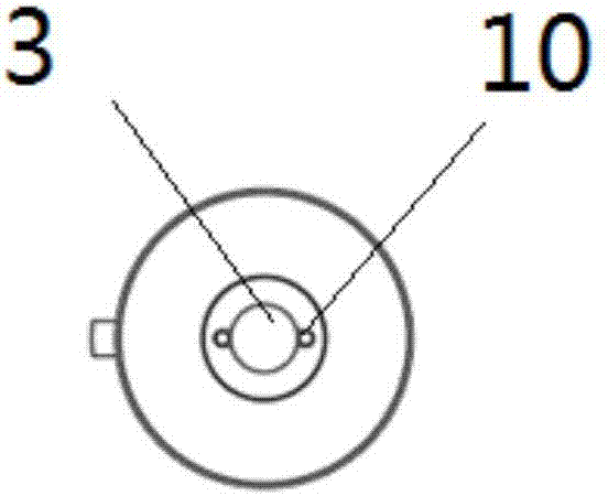
[0029] Such as Figure 1~Figure 4 As shown, a signal transmission device of an ultrasonic endoscope, which includes an inner conductor 1, an outer conductor 2 and a rotating shaft 3 connected to an external drive mechanism, the rotating shaft 3 is a hollow structure, and the ultrasonic probe passes through the rotating shaft The shaft 3 protrudes and is fixedly connected with the rotating shaft 3, the inner conductor 1 is sleeved outside the rotating shaft 3 and connected with the rotating shaft 3, the outer conductor 2 is sleeved outside the inner conductor 1, and the A conductive liquid 5 is filled between the inner conductor 1 and the outer conductor 2; the inner conductor 1 is electrically connected to the ultrasonic probe.

[0030] Such as Figure 1~Figure 4 As shown, the signal transmission device of the ultrasonic endoscope includes an insulating cover 6 and a shielding shell 4, the insulating cover 6 is arranged at the end of the outer conductor 2, and the outer condu...

Embodiment 2

[0035] Such as Figure 5 As shown, an ultrasonic endoscope includes an ultrasonic host, an ultrasonic probe, an external display device and the signal transmission device described in Embodiment 1, the outer conductor is electrically connected to the ultrasonic host, and the ultrasonic probe is connected to the rotating shaft Fixed connection, the ultrasonic probe is electrically connected with the inner conductor, the ultrasonic host sends out a signal, passes through the signal transmission device of the ultrasonic endoscope, reaches the ultrasonic probe, sends out ultrasonic waves, and the ultrasonic probe receives the ultrasonic echo, passes through the pressure The electric effect produces echo electrical signals, which are displayed in the form of images on the external display device after being processed by the ultrasonic host.


PUM


Abstract

The invention provides an ultrasonic endoscope and a signal transmission device thereof. The signal transmission device comprises an inner conductor, an outer conductor and a rotating shaft for connecting an outer driving mechanism and an outer driving mechanism. A probe of the ultrasonic endoscope is fixedly connected with the rotating shaft, the rotating shaft is sleeved with the inner conductor, the inner conductor is connected with the rotating shaft, and is sleeved with the outer conductor, and the portion between the inner conductor and the outer conductor is filled with conductive liquid; the inner conductor is electrically connected with the probe of the ultrasonic endoscope. According to the technical scheme, signal transmission between rotating electrodes is carried out through the conductive liquid; as the conductor rotates in liquid, mechanical friction is quite small, the service life is greatly prolonged, and the requirement of the high rotating speed can be met; conductive impedance is constant, the signal integrity is better, interference signals are reduced, better pattern information is obtained, and the signal transmission device is particularly suitable for transmission of high-frequency signals; the structure is simple, the processing requirements are low, and the reliability is high.

Description

technical field [0001] The invention belongs to the technical field of medical instruments, in particular to an ultrasonic endoscope and a signal transmission device thereof. Background technique [0002] In modern medical interventional diagnosis and treatment, ultrasonic endoscope can use the biopsy channel of electronic endoscope to send a miniature ultrasonic scanning probe into the human body. Tomographic images of organ walls to discover early cancers and tiny tumors are a common method for diagnosing human internal organ lesions. [0003] Ultrasound scanning requires the probe to rotate 360 ​​degrees at high speed to obtain a complete tomographic image. In existing products, most of them use brush slip rings as transmission devices to transmit signals. However, the brush slip ring wears seriously under long-term high-speed rotation conditions, and its service life is short; at the same time, because the brush impedance is not constant during the rotation process, it...

Claims


Application Information

Patent Timeline
Patent Type & Authority Applications(China)
IPC IPC(8): A61B8/12A61B8/00
CPCA61B8/12A61B8/56
Inventor 白晓淞
Owner INNERMEDICAL CO LTD
Learn More