Liquid return preventing chimney

A chimney and anti-return technology, applied in the direction of smoke removal, combustion method, cleaning method and utensils, etc., to achieve the effect of convenient transportation, convenient transportation, convenient disassembly and assembly

Pending Publication Date: 2017-11-03
BC P INC CHINA NAT PETROLEUM CORP +1
View PDF8 Cites 2 Cited by
  • Summary
  • Abstract
  • Description
  • Claims
  • Application Information

AI Technical Summary

Problems solved by technology

[0003] The purpose of the invention is to overcome the problem of backflow of condensed liquid on the chimney wall existing in the chimney of the prior art

Method used


Image

  • Liquid return preventing chimney
  • Liquid return preventing chimney
  • Liquid return preventing chimney

Examples


Embodiment 1

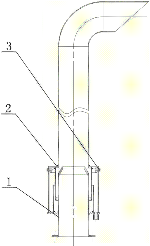
[0019] Such as figure 1 As shown, it includes a fixed part 1 of the chimney, a detachable part 2 of the chimney and a fastener 3, and the detachable part 2 of the chimney is fixed on the upper part of the fixed part 1 of the chimney through the fastener 3. When the equipment needs to be used or moved, the detachable part 2 of the chimney is directly connected or removed, and the fastener 3 is installed on the fixed part 1 of the chimney, which is convenient for transportation.

Embodiment 2

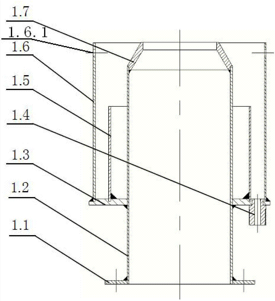
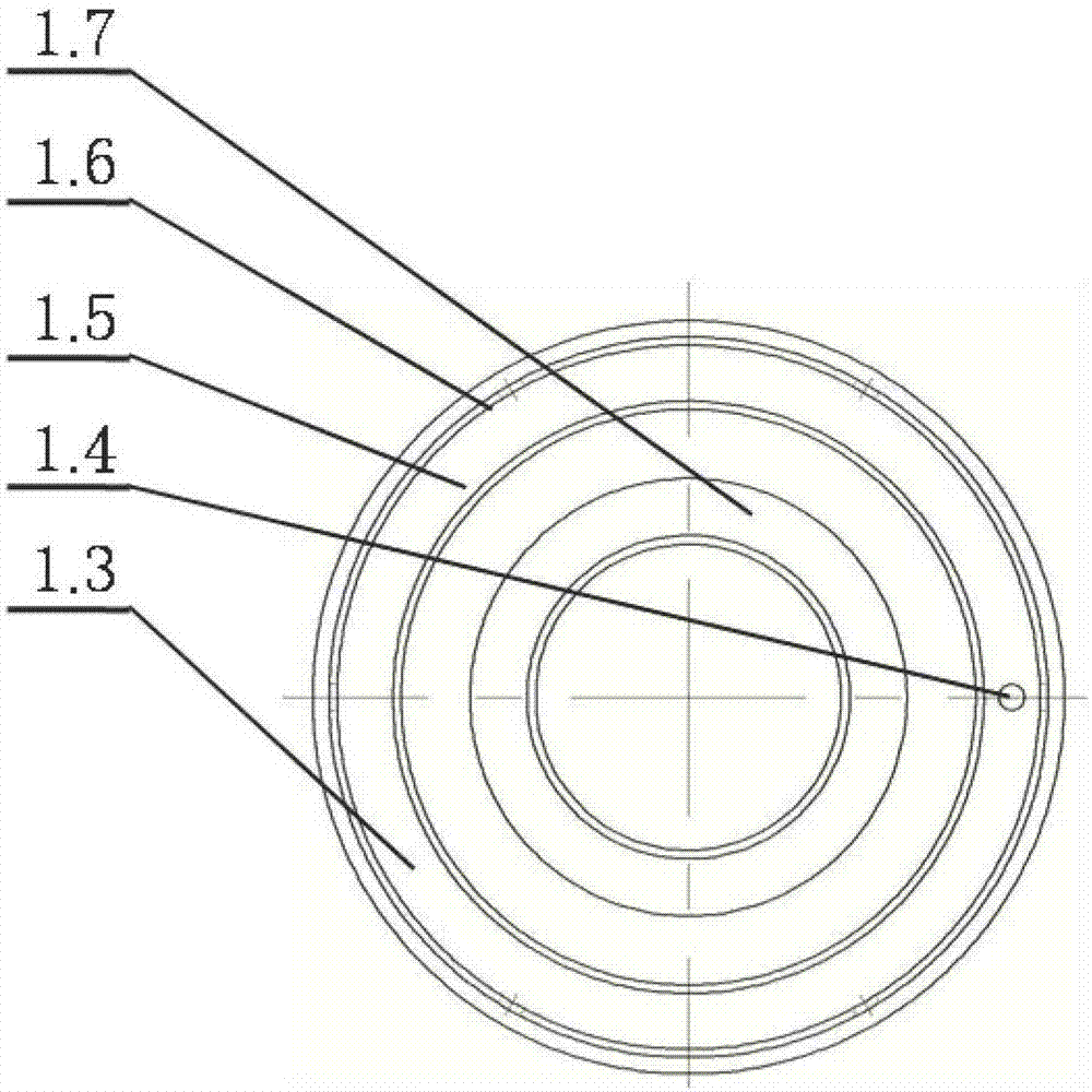
[0021] Such as figure 1 , figure 2 , image 3 , Figure 4 with Figure 5 As shown, on the basis of Example 1, the chimney fixed part 1 includes a flange 1.1, a draft pipe 1.2, a bottom plate 1.3, a liquid discharge port 1.4, a liquid sealing shell 1.5, an outer shell 1.6 and a draft nozzle 1.7, the The top and bottom of the above-mentioned diversion pipe 1.2 are respectively connected to the diversion nozzle 1.7 and the flange 1.1, the bottom plate 1.3 is sleeved on the outside of the middle part of the diversion pipe 1.2, and the liquid seal shell 1.5 and the outer shell 1.6 are vertically sleeved on the diversion pipe from inside to outside. The outer side and the bottom of the tube 1.2 are connected to the upper part of the base plate 1.3, and the drain port 1.4 is connected to the lower part of the base plate 1.3 and is located between the liquid seal shell 1.5 and the outer shell 1.6, and the upper part of the outer shell 1.6 has a light hole 1.6.1. The detachable pa...


PUM


Abstract

The invention belongs to the technical field of exhaust gas emission equipment in the field of oil fields, chemical engineering, metallurgy and medicine, and particularly relates to a liquid return preventing chimney. The chimney comprises a chimney fixed part, a chimney detachable part and a fastener. The chimney detachable part is fixed to the upper portion of the chimney fixed part through the fastener. The problems that chimney wall congealed liquid flows back and operation sites are polluted according to a traditional chimney are solved, and the liquid return preventing chimney has the advantages that the effect of preventing chimney wall congealed liquid backflow is achieved, assembly and disassembly are convenient, and conveying is convenient.

Description

technical field [0001] The invention belongs to the technical field of tail gas discharge equipment in the fields of oil field, chemical industry, metallurgy and medicine, and in particular relates to a liquid return preventing chimney. Background technique [0002] When condensing and recovering high-temperature gas, in order to improve the condensation efficiency, an induced draft fan is often used to exhaust the exhaust gas at the end of the process. Affected by changes in the high-temperature gas flow rate, when a traditional chimney is connected to the tail of the induced draft fan to work, the liquid condensed on the chimney wall flows down the chimney tube wall, causing the induced draft fan to not work normally. For example, increasing the air volume of the induced draft fan can avoid condensation The liquid on the pipe wall returns, but the liquid will be blown out from the chimney and pollute the work site. For this reason, a new chimney is needed, which can avoid ...

Claims


Application Information

Patent Timeline
Patent Type & Authority Applications(China)
IPC IPC(8): F23J11/00F23J13/00B08B15/00
CPCF23J11/00F23J13/00B08B15/00
Inventor 王玉陈在君李前春张新发胡东锋郭亮权银虎李世勇徐军张军峰
Owner BC P INC CHINA NAT PETROLEUM CORP
Why Eureka
Try Eureka