
High-precision absolution relative gravity measurement instrument driven by optical force

A gravity measurement and high-precision technology, which is applied in the field of high-precision gravity measuring instruments and high-precision absolute relative gravity measuring instruments, can solve the problems of small measurement dynamic range, low measurement accuracy, long absolute measurement cycle, etc., and achieve the measurement dynamic range Large, high-precision measurement, wide dynamic range effect

Active Publication Date: 2017-11-03
ZHEJIANG UNIV
View PDF8 Cites 6 Cited by
  • Summary
  • Abstract
  • Description
  • Claims
  • Application Information

AI Technical Summary

Problems solved by technology

[0004] The disadvantage of the relative gravimeter is that it can only measure the relative change of gravity, and cannot give the absolute value of the acceleration of gravity, so the accuracy of the relative gravimeter depends on the calibration of the absolute gravimeter
[0005] At present, the absolute gravimeter has high measurement accuracy, but the absolute measurement period is long, the measurement dynamic range is small, and the application environment requirements are high. The relative gravimeter has a large measurement dynamic range, but the measurement accuracy is low, so the development can realize high-precision measurement of absolute gravity. Acceleration, and can measure the relative acceleration of gravity in real time, it is very important to measure the gravimeter with a large dynamic range

Method used


Image

  • High-precision absolution relative gravity measurement instrument driven by optical force
  • High-precision absolution relative gravity measurement instrument driven by optical force
  • High-precision absolution relative gravity measurement instrument driven by optical force

Examples


Embodiment Construction

[0017] The present invention will be further described below in conjunction with the accompanying drawings and specific embodiments.

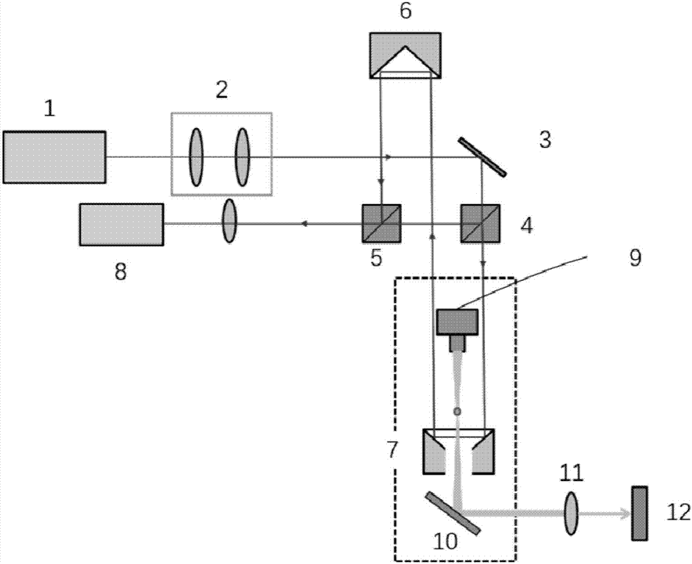
[0018] refer to figure 1 , The gravimeter of the present invention performs high-precision gravity measurement based on the optical force effect, and can simultaneously realize absolute gravity measurement and relative gravity measurement. The present invention adopts the device as shown in the figure, including a first laser 1, a collimating beam expander system 2, a mirror 3, a first beam splitter 4, a second beam splitter 5, a falling prism 6, a reference prism 7, a photoelectric Detector 8 , second laser 9 , steering lens 10 , focusing lens 11 and four-quadrant detector 12 . Wherein the first laser 1, the collimating beam expander system 2 and the reflector 3 are on the same horizontal line in turn, and the first beam splitter 4, the second beam splitter 5 and the photodetector are on the same horizontal line in turn and are located below ...


PUM

PropertyMeasurementUnit
Diameteraaaaaaaaaa

Abstract

The invention discloses a high-precision absolution relative gravity measurement instrument driven by optical force. The measurement instrument comprises a first laser, a collimation beam extending system, a reflection mirror, a first beam divider, a second beam divider, a falling body prism, a reference prism, a photoelectric detector, a second laser, a steering lens, a focusing lens and a four-quadrant detector. A hollow photonic crystal fiber light trap system is arranged between the second laser and the steering lens. Micro particles are arranged in the light trap system. According to the invention, high-precision gravity accelerated speed is achieved by use of optical force effects; when the gravity accelerated speed is precisely measured, the measured dynamic range is quite wide; by use of different parts to work, high precision measurement of the absolute gravity accelerated speed can be achieved and real-time measurement of the relative gravity accelerated speed can be achieved; the measurement dynamic range is wide; and the measurement instrument is suitable for aerospace and sailing field.

Description

technical field [0001] The invention belongs to the technical field of high-precision gravity measurement, and relates to a high-precision gravity measurement instrument, in particular to a high-precision absolute relative gravity measurement instrument driven by optical force, which can simultaneously realize absolute gravity measurement and relative gravity measurement. Background technique [0002] The photodynamic effect refers to the interaction between light carrying energy and momentum and matter, resulting in the exchange of momentum, which is manifested as the effect of light exerting force on objects. The magnitude of the force is equal to the change of the momentum of the object per unit time caused by the light, and thus can cause the displacement and speed of the object to change. The force generated by light is directly proportional to the light intensity, the stronger the light intensity and the smaller the mass of the irradiated object, the more obvious this ...

Claims


Application Information

Patent Timeline
IPC IPC(8): G01V7/00G01V7/16
CPCG01V7/00G01V7/16
Inventor 黄腾超陈傲庞斌贺青刘承舒晓武
Owner ZHEJIANG UNIV
Learn More