

Layout optimization method and deice, terminal and storage medium
A layout optimization technology to be optimized, applied in the FPGA field, can solve problems such as unfavorable self-developed electronic market development, achieve the effect of enhancing user experience and improving layout effect
- Summary
- Abstract
- Description
- Claims
- Application Information
AI Technical Summary
Problems solved by technology
Method used
Image

Examples
no. 1 example
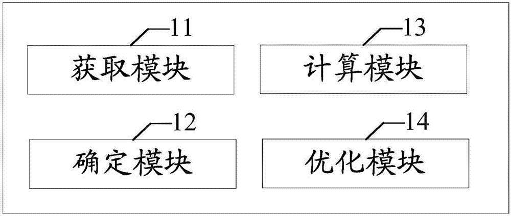
[0078] figure 1 This is a structural block diagram of the layout optimization device provided by the first embodiment of the present invention, which is represented by figure 1 It can be seen that the layout optimization device provided in this embodiment includes:
[0079] The obtaining module 11 is used to analyze the netlist to be optimized and obtain the critical path;
[0080] The determining module 12 is used to traverse the instances on the critical path and determine the instances to be copied;
[0081] The calculation module 13 is used to calculate the insertion position of the instance to be copied according to a preset algorithm;
[0082] The optimization module 14 is used to copy the instance to be copied and insert it into the corresponding insertion position to generate an optimized design netlist.
[0083] In some embodiments, the acquisition module 11 in the above embodiments is used to:
[0084] Calculate the routing delay of each path in the netlist to be optimized;
[0...
no. 2 example
[0182] This example is aimed at the layout algorithm, and based on the current mainstream layout algorithm, the logic unit used in the design is abstracted as an instance.
[0183] Such as Figure 5 As shown in (1), when the output of a certain instance is connected to multiple instances, and the position of the latter instance is placed far away, after placement, the best position of a is generally between them. At this time, e and c may be separated If a is far away, it will lead to longer wiring delay and poor timing here. For such paths, this application calls them critical paths.
[0184] In this example, in response to this situation, without changing the original logic, the middle a is copied and inserted into the design netlist, which is placed reasonably by the timing drive, and the result is Figure 5 As shown in (2), the actual distance from a to c and e is shorter, and the wiring from b and d to a is more direct, thereby effectively improving the timing.
[0185] Specific...
no. 3 example
[0203] Such as Figure 8 As shown, the layout optimization method provided by this embodiment includes the following steps:
[0204] S801: Collect instances;
[0205] Traverse the design netlist and collect the instances whose slack value is less than worst slack (worst slack value) + margin into the container. Among them, worst slack is determined by the original design netlist, and margin is a constant value.
[0206] S802: sorting of instances;
[0207] The sorting rules are as follows:
[0208] 1. Sort the instances according to the slack value from small to large, the purpose is to arrange the instances on the same critical path adjacently, and give priority to the critical path with the smaller slack value.
[0209] 2. For the instances on the same critical path, sort them according to the level of the critical pin of the instance itself from low to high. The purpose is to give priority to the instance with a lower pin level, which can improve optimization efficiency.
[0210] S808...
PUM
 Abstract
Description
Claims
Application Information