Method, device and system for tracking rigid body
A rigid body, three-dimensional position technology, applied in the computer field, can solve the problems of low positioning accuracy, large calculation amount of feature matching algorithm, and inaccurate positioning.
- Summary
- Abstract
- Description
- Claims
- Application Information
AI Technical Summary
Problems solved by technology
Method used
Image

Examples
Embodiment 1
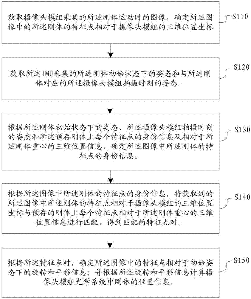
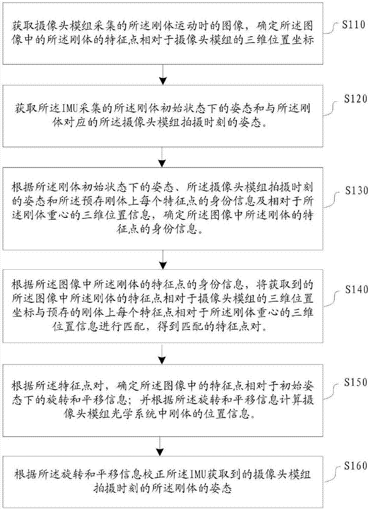
[0054] figure 1 is a flow chart of a rigid body tracking method according to an embodiment of the present invention, such as figure 1 as shown,
[0055] Before step S110, the inertial measurement sensor IMU is arranged on the rigid body, and the identity information of each feature point on the rigid body and the three-dimensional position information relative to the center of gravity of the rigid body are pre-stored;
[0056] In one embodiment of the present invention, the inertial measurement sensor IMU is arranged at the center of gravity of the rigid body, and the prestored three-dimensional position information of each feature point on the rigid body with respect to the center of gravity of the rigid body refers to the position of each feature point on the rigid body. The geometric three-dimensional position information of each feature point relative to the rigid center of gravity includes the identity information of each feature point (for example, the specific number 1...
Embodiment 2
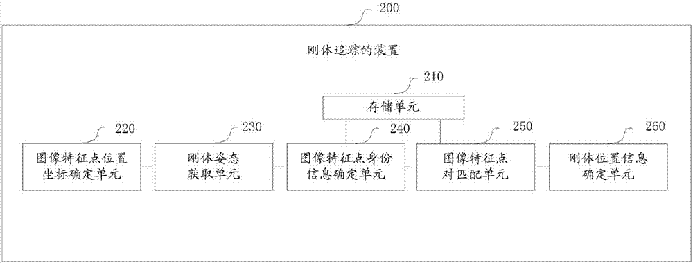
[0085] image 3 It is a structural schematic diagram of a rigid body tracking device according to an embodiment of the present invention, such as image 3 Shown, a kind of device of rigid body tracking, described rigid body comprises a plurality of feature points, and inertial measurement sensor IMU is arranged on described rigid body, and described device comprises:
[0086] The storage unit 210 is used to pre-store the identity information of each feature point on the rigid body and the three-dimensional position information relative to the center of gravity of the rigid body;
[0087] An image feature point position coordinate determining unit 220, configured to acquire the image captured by the camera when the rigid body moves, and determine the three-dimensional position coordinates of the feature point of the rigid body in the image relative to the camera;
[0088] Rigid body attitude acquisition unit 230, configured to acquire the attitude of the rigid body in the init...
Embodiment 3
[0102] Figure 5 is a schematic diagram of a rigid body tracking system according to an embodiment of the present invention, such as Figure 5 As shown, the system 30 includes a camera 310, a rigid body 320 (in this embodiment, the rigid body refers to a head-mounted display device) and a control terminal 330, wherein an IMU340 is arranged on the rigid body (in this embodiment, Set the IMU at the center of gravity of the rigid body); in practical applications, the rigid body can be any kind of virtual reality device.
[0103] The camera 310 is configured to collect images of the rigid body 320 and send the images of the rigid body 320 to the control terminal 330;
[0104] The IMU340 is configured to collect the attitude of the rigid body 320 in its initial state and the attitude of the camera 310 corresponding to the rigid body 320 at the shooting time, and send the attitude to the control terminal 330;
[0105]The control terminal 330 is used to obtain the image captured by...
PUM
 Abstract
Description
Claims
Application Information
 - R&D
- Intellectual Property
- Life Sciences
- Materials
- Tech Scout
- Unparalleled Data Quality
- Higher Quality Content
- 60% Fewer Hallucinations
Browse by: Latest US Patents, China's latest patents, Technical Efficacy Thesaurus, Application Domain, Technology Topic, Popular Technical Reports.
© 2025 PatSnap. All rights reserved.Legal|Privacy policy|Modern Slavery Act Transparency Statement|Sitemap|About US| Contact US: help@patsnap.com