Straight-line servo driver and robot

A servo driver and linear technology, applied in the direction of electromechanical devices, electric components, control mechanical energy, etc., can solve the problems of large space occupied by the servo driver, many internal components of the weight of the linear servo motor, and low transmission efficiency, so as to improve the transmission efficiency, The effect of improving detection efficiency and accuracy and reducing weight

Pending Publication Date: 2017-11-03
苏州瑞步康医疗科技有限公司
View PDF7 Cites 0 Cited by
  • Summary
  • Abstract
  • Description
  • Claims
  • Application Information

AI Technical Summary

Problems solved by technology

[0005] Therefore, the technical problem to be solved by the present invention is to overcome the linear servo driver in the prior art that needs to be provided with multiple sets of bearings, which causes the weight of the linear servo motor and many internal components, resulting in a large space occupied by the servo driver and low transmission efficiency.

Method used


Image

  • Straight-line servo driver and robot
  • Straight-line servo driver and robot
  • Straight-line servo driver and robot

Examples


Embodiment 1

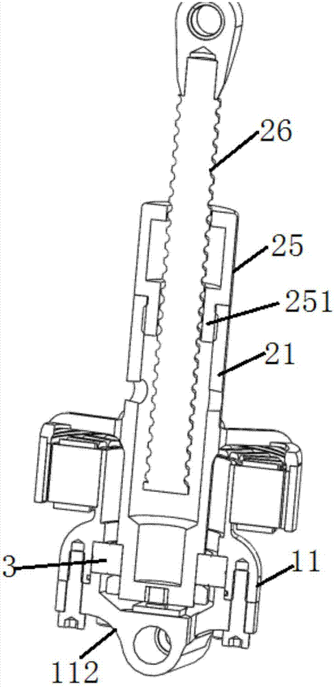
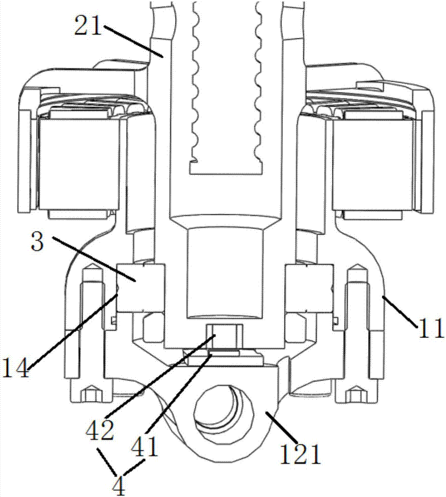
[0068] This embodiment provides a linear servo driver, such as figure 1 and figure 2 As shown, it includes a stator assembly 1 , a rotor assembly 2 , a detection assembly 4 and a bearing 3 .

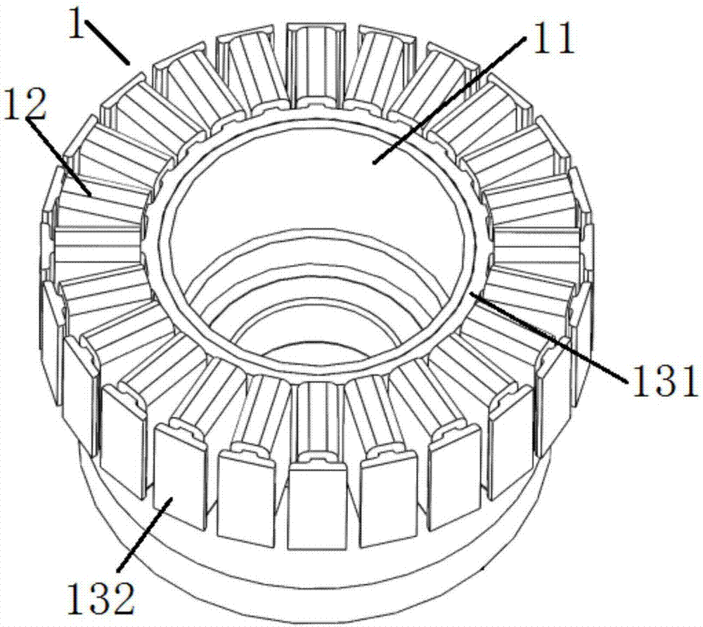
[0069] like image 3 , Figure 4 and Figure 7 As shown, the stator assembly 1 includes a first housing 11 , a coil 12 and a soft magnet 13 . The first housing 11 includes a cover body 111 with a first inner cavity and an end cover 112 . The two ends of the cover body 111 are respectively provided with a first opening and a second opening for connecting the first inner cavity with the outside world. The end cover 112 Removably secured to the second opening, for example with a screw or bolt assembly. The end cover 112 forms a fixed end at the second opening of the first housing 11 , and the end cover 112 is detachably arranged to facilitate the installation or removal of components located in the first inner cavity.

[0070] like image 3 and Figure 4 As shown, the soft magnetic...

Embodiment 2

[0086] This embodiment provides a linear servo driver. Compared with the driver provided in Embodiment 1, the differences are:

[0087] In addition to the magnetic sensing element 41 and the second permanent magnet 42 in Embodiment 1, the detection assembly 4 can also be of other structures. For example, the detection component 4 is replaced by a photoelectric encoder, the second permanent magnet 42 is replaced by a code disc, and the magnetic sensitive element 41 is replaced by a photosensitive element. At this time, the photosensitive element illuminates the code disc with light, and the light passes through the code disc and is reflected back to the photosensitive element. , the photosensitive element detects the change in the intensity of the light absorbed by the code disc, thereby detecting the rotation angle or speed of the second casing 21 relative to the first casing 11 . Alternatively, the detection component 4 can also be replaced by other types of encoders. It onl...

Embodiment 3

[0089] This embodiment provides a linear servo driver. Compared with the driver provided in Embodiment 1 or Embodiment 2, the difference is that the lead screw nut 25 is not provided with an annular flange 251, but only includes a nut body. The orientation of the nut body is The end surface of the end cover 112 is directly fixed on the first opening of the second housing 21, for example, by using screws or bolts, or other fasteners. Alternatively, the lead screw nut 25 can be replaced with an existing flange, the flange is sleeved and rotatably matched with the lead screw, and the flange is fixed on the end face of the first housing 11 where the first opening is located, Through the rotational cooperation between the flange plate and the lead screw 26, when the flange plate rotates, the lead screw 26 moves linearly.

[0090] As an alternative embodiment, the rotor assembly 2 may not be provided with the above-mentioned lead screw nut 25 or flange, and the inner wall surface of...


PUM


Abstract

The invention discloses a straight-line servo driver and a robot. The driver comprises a stator assembly, a rotor assembly, a detection assembly and at least one bearing, wherein the stator assembly is provided with a first shell; the rotor assembly is provided with a second shell and a lead screw arranged inside the second shell in a penetrating manner; the end, stretching into the interior of the first shell, of the second shell is rotatably arranged on the first shell through the at least one bearing; a detected part and a detecting piece in the detection assembly are fixed on the second shell and the first shell respectively and are close to the bearing. The robot comprises a first arm, a second arm and the driver for driving the first arm to rotate on the second arm. According to the driver, the rotation points, relative to the first shell, of the detection assembly and the second shell are both concentrated on the position of the bearing, the bearing can bear the radial and axial load of the rotor assembly and guarantees relative position of the detection assembly, a plurality of bearings do not need to be arranged, the quantity of components is reduced, the driver is convenient to process and mount, and the self weight of the driver is reduced, so that the frictional resistance is reduced, and the transmission efficiency is improved.

Description

technical field [0001] The present invention relates to the technical field of motors, in particular to a linear servo driver and a robot. Background technique [0002] At present, collaborative robots often operate or move in the same space as workers, which requires the robot to not be too heavy, otherwise it will threaten the safety of workers. Especially wearable robots, such as electric prosthetic limbs and electric power-assisted exoskeleton robots, must be light in weight so that they can be easily worn by people, and at the same time reduce the threat to the personal safety of the user and the people around the user, and it is convenient to reduce the overall performance of the robot. power consumption and prolong the battery life of the robot. In robots, servo drives account for a large proportion. [0003] The structure of the linear servo motor used in the robot is mostly like the linear actuator disclosed in Chinese patent document CN102780311A, which includes ...

Claims


Application Information

Patent Timeline
Patent Type & Authority Applications(China)
IPC IPC(8): H02K7/06H02K7/14
CPCH02K7/06H02K7/145
Inventor 王世乾
Owner 苏州瑞步康医疗科技有限公司
Why Eureka
Try Eureka