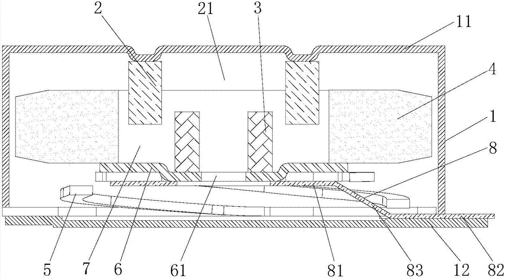
Linear vibration motor

A linear vibration and motor technology, applied in the direction of electromechanical devices, electrical components, etc., can solve the problems of not meeting the application requirements of multi-frequency point vibration tactile feedback, low utilization efficiency of magnetic force lines of magnets, difficulty in controlling assembly accuracy, etc., to save The effect of external positioning tooling, improving tactile experience, and improving utilization efficiency

Inactive Publication Date: 2017-11-03
GOERTEK INC
View PDF12 Cites 6 Cited by
  • Summary
  • Abstract
  • Description
  • Claims
  • Application Information

AI Technical Summary

Problems solved by technology

[0005] However, the existing linear vibration motor has the following defects. 1. The utilization efficiency of the magnetic force lines of the magnet is low, which affects the overall tactile experience
2. The assembly process of the existing motor is complicated, especially when the coil and the mass block are assembled as vibration components, an external positioning tool is required between the two to ensure coaxial assembly, the assembly steps are cumbersome, and it is difficult to control the assembly accuracy
3. The existing linear vibration motor is only suitable for vibration experience at a single frequency point, and does not meet the application requirements for tactile feedback of multi-frequency point vibration

Method used


Image

  • Linear vibration motor
  • Linear vibration motor
  • Linear vibration motor

Examples


Embodiment Construction

[0043] In the following description, for purposes of explanation, numerous specific details are set forth in order to provide a thorough understanding of one or more embodiments. It may be evident, however, that these embodiments may be practiced without these specific details. In other instances, well-known structures and devices are shown in block diagram form in order to facilitate describing one or more implementations.

[0044] The "mass block" used in the description of the following specific embodiments may also be referred to as "counterweight block", which refers to one of the components that cooperate with magnets or coils in the motor casing to vibrate as a vibrator assembly. In addition, the present invention is mainly used to improve the linear vibration motor used in the description, which may also be called a Y-direction vibration motor. However, for the convenience of expression, in the description of the following embodiments, a linear vibration motor is spec...


PUM


Abstract

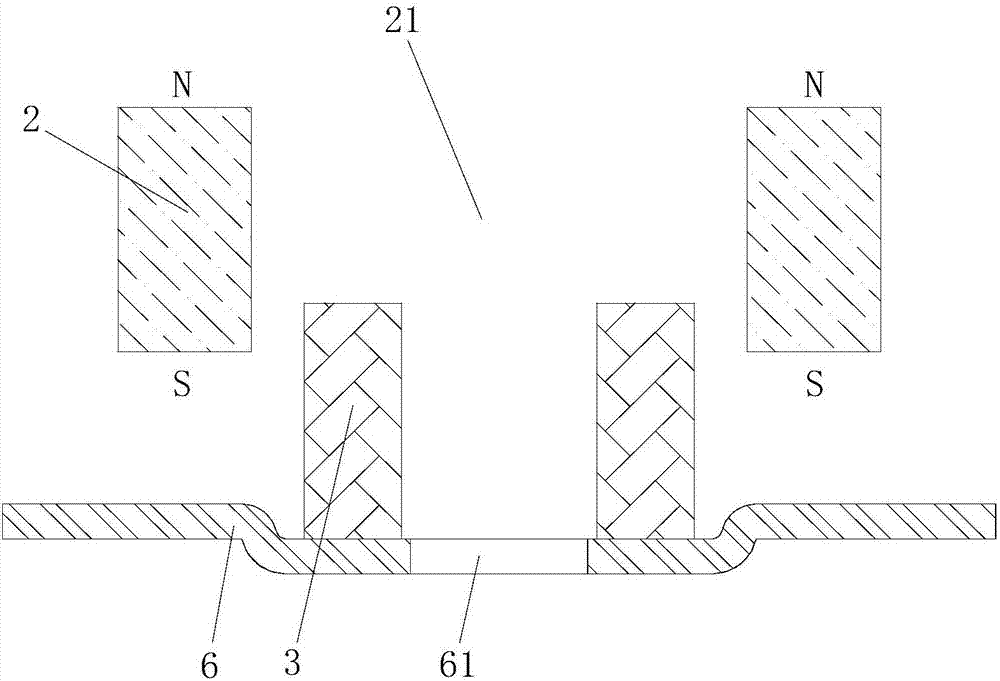
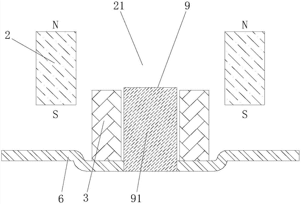
The invention discloses a linear vibration motor which comprises a stator assembly, a vibrator assembly and an elastic supporting part, wherein the stator assembly comprises a shell with an accommodating cavity and a magnet positioned in the accommodating cavity and combined and fixed with the shell; the magnet comprises a hollow part; the vibrator assembly comprises a coil arranged on a concentrating flux plate and mass blocks surrounding the periphery of the coil; the hollow part extends along a vibrating direction of the vibrator assembly; when the vibrator assembly vibrates, the coil vibrates along with the vibrator assembly and is inserted into the hollow part of the magnet; the elastic supporting part is configured to suspend the vibrator assembly in the accommodating cavity of the shell; and the concentrating flux plate further comprises a through hole which corresponds to an inner cavity of the coil and runs through the upper surface and the lower surface of the concentrating flux plate. According to the linear vibration motor provided by the invention, the structure can utilize magnetism of the magnet to the greatest extent; utilization efficiency of the coil for magnetic force lines of the magnet is promoted; an electromagnetic driving force of the motor is promoted; and the assembling process is simple and convenient, and assembling accuracy is high, so that the motor can obtain better vibration performance.

Description

technical field [0001] The invention belongs to the technical field of electronic products. More specifically, it relates to a linear vibration motor. Background technique [0002] With the development of communication technology, portable electronic devices, such as mobile phones, tablet computers, smart wearable devices, multimedia entertainment devices, etc., have become a necessity in people's lives. In these electronic devices, a miniature linear vibration motor is usually used for system feedback, such as vibration feedback when clicking a touch screen. [0003] A linear vibration motor is a component that uses the principle of electromagnetic force to convert electrical energy into mechanical vibration. Conventional linear vibration motors are usually installed in mobile communication terminals, portable terminals, etc., and are usually installed on the edge of the device, and receive vibration Vibrates in a direction perpendicular to the object. [0004] Existing ...

Claims


Application Information

Patent Timeline
Patent Type & Authority Applications(China)
IPC IPC(8): H02K33/18H02K33/02
CPCH02K33/02H02K33/18
Inventor 毛东升张新众臧玮晔
Owner GOERTEK INC
Why Eureka
Try Eureka