
Flexible tail end traction rehabilitation robot

A rehabilitation robot and terminal traction technology, applied in passive exercise equipment, physical therapy and other directions, can solve the problems of increasing patient pain, patient injury, inaccurate adjustment of length, etc., to reduce rehabilitation time, labor intensity, occupation, etc. small space effect

Active Publication Date: 2017-11-07
HEFEI UNIV OF TECH
View PDF8 Cites 6 Cited by
  • Summary
  • Abstract
  • Description
  • Claims
  • Application Information

AI Technical Summary

Problems solved by technology

[0003] The existing rehabilitation training equipment has the following deficiencies: 1) the equipment is bulky and requires a special rehabilitation training room; 2) the existing rehabilitation equipment is complicated to manufacture and expensive; 3) the existing rehabilitation equipment cannot be flexibly adjusted to suit different needs. The patient's own size cannot adjust the trajectory very well, and the existing part of the adjustable design is also very difficult to adjust. It is necessary to adjust the length of multiple joints. If the length is not adjusted accurately, it will cause harm to the patient; 4) Existing rehabilitation equipment is not applicable For patients with severe decline in physical ability, it is very inconvenient to repeatedly transport patients; 5) The existing rehabilitation equipment is rigid structure, forcibly pulling patients to do rehabilitation exercises, which is likely to cause secondary injuries and increase the pain of patients

Method used


Image

  • Flexible tail end traction rehabilitation robot
  • Flexible tail end traction rehabilitation robot
  • Flexible tail end traction rehabilitation robot

Examples


Embodiment Construction

[0026] The embodiments of the present invention are described in detail below. This embodiment is implemented on the premise of the technical solution of the present invention, and detailed implementation methods and specific operating procedures are provided, but the protection scope of the present invention is not limited to the following implementation example.

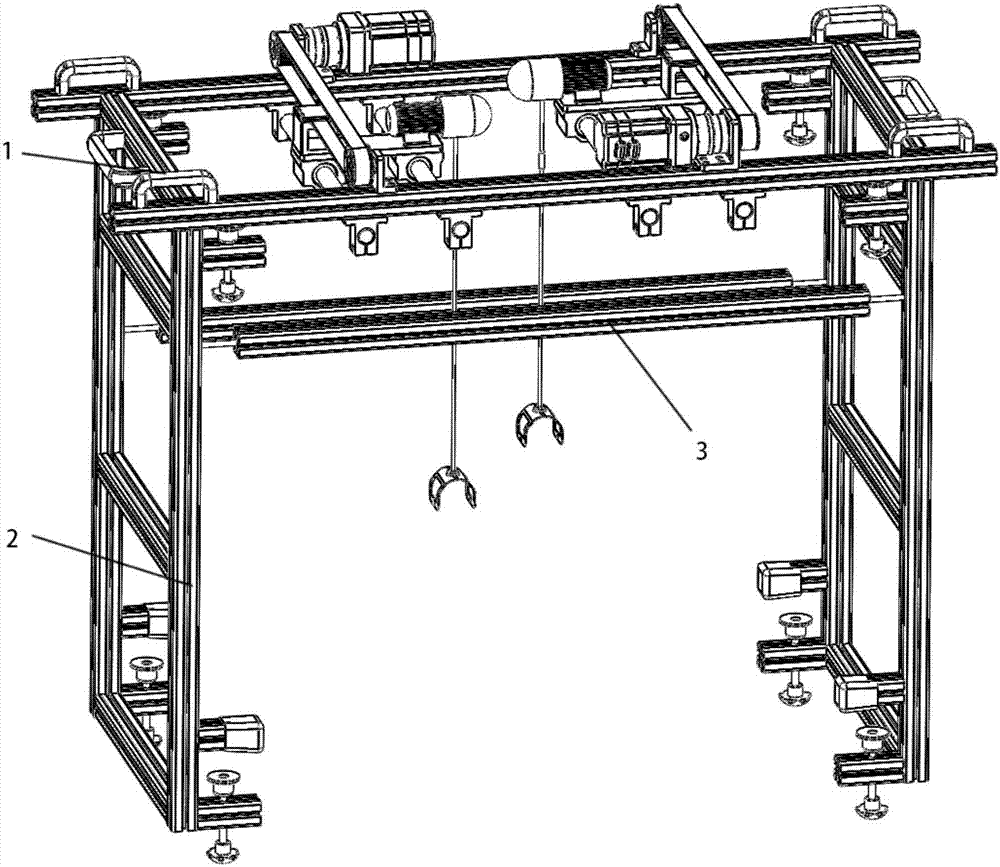
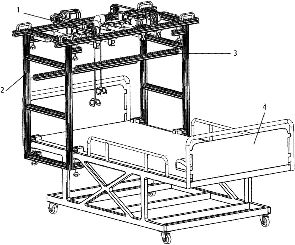
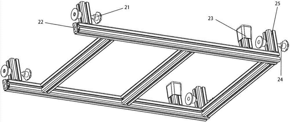
[0027] see Figure 1 to Figure 5 , this embodiment discloses a flexible terminal traction rehabilitation robot, including a mounting bracket 2 and a traction mechanism 1 arranged on the mounting bracket 2, the bottom of the mounting bracket 2 is clamped on the hospital bed 4, and the bottom of the mounting bracket 2 is The four corners are all provided with clamping parts, and the clamping parts include an upper clamping plate 23, a lower clamping plate 25, and a clamping bolt 24. The upper clamping plate 23 and the lower clamping plate 25 are arranged up and down oppositely and leave a gap. The tightening bolt 24...


PUM


Abstract

The invention discloses a flexible tail end traction rehabilitation robot. The flexible tail end traction rehabilitation robot comprises a mounting rack and a traction mechanism. The bottom of the mounting rack is clamped on a sickbed. The traction mechanism comprises two traction units. Each traction unit comprises a slide block component, a guide rail, an electric hoist and a foot fixing rack. The guide rail is installed on a frame. The slide block component is arranged on the guide rail and is slidably connected with the guide rail. The electric hoist is installed on the slide block component. The food fixing rack is installed at the tail end of a traction rope of the electric hoist. A pulling force sensor and an angle sensor are installed on the traction rope. The slide block component is driven to slide along the corresponding guide rail by a driving mechanism to drive the electric hoist and the traction rope on the electric hoist to move back and forth. The foot fixing rack moves back and forth along with the traction rope and moves in the vertical direction under the effect of contraction and release of the traction rope to simulate the walking track of the foot of a patient at the same time. The flexible tail end traction rehabilitation robot has the advantage that flexible traction can be conducted on the foot of the patient to avoid a secondary injury.

Description

technical field [0001] The invention relates to the field of medical devices, in particular to a rehabilitation robot with flexible end traction. Background technique [0002] Rehabilitation robots are a combination of industrial robots and medical robots. The 1980s was the initial stage of rehabilitation robot research, and the United States, Britain and Canada were in the leading position in the world in the field of rehabilitation robot research. After 990, the research on rehabilitation robots entered a period of comprehensive development. At present, the research of rehabilitation robot mainly focuses on several aspects such as rehabilitation manipulator, hospital robot system, intelligent wheelchair, prosthesis and rehabilitation robot. [0003] The existing rehabilitation training equipment has the following deficiencies: 1) the equipment is bulky and requires a special rehabilitation training room; 2) the existing rehabilitation equipment is complicated to manufact...

Claims


Application Information

Patent Timeline
IPC IPC(8): A61H1/02
CPCA61H1/0222A61H1/0259A61H2201/0142A61H2201/1207A61H2203/0456
Inventor 黄康张怡然赵韩陈小龙何春生朱胤斐马加奇
Owner HEFEI UNIV OF TECH
Learn More