
Circuit board edging system

A circuit board and edge grinding technology, which is applied to machine tools, grinders, grinding racks, etc. suitable for grinding workpiece edges, can solve the problems of circuit board production line length, etc., and achieve the effect of reducing the floor space.

Pending Publication Date: 2017-11-07
ANHUI DASHENG ELECTRONICS
View PDF7 Cites 2 Cited by
  • Summary
  • Abstract
  • Description
  • Claims
  • Application Information

AI Technical Summary

Problems solved by technology

[0003] The purpose of the present invention is to solve the problem that the circuit board edging system in the prior art requires manual rotation of the circuit board or the production line is very long. Therefore, a circuit board edging system is provided here

Method used


Image

  • Circuit board edging system
  • Circuit board edging system

Examples


Embodiment Construction

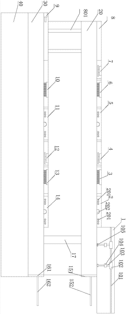
[0023] Such as Figure 1-2 As shown, a circuit board edging system includes a frame, a conveying device 19, a feeding device 1, an edging device, a rotating device, a dust cleaning device, a pushing device 9, and a control cabinet 40. The edging device includes a first grinding Edge device, second edging device, third edging device, fourth edging device, rotating device includes first rotating device 4, second rotating device 7, third rotating device 12, dust cleaning device includes first dust cleaning device Device 3 , second dust removal device 6 , third dust removal device 10 , and fourth dust removal device 13 .

[0024] The conveying device 19 is arranged on the frame, and in this solution, the conveying device is a conveying roller 19 . The rack includes an upper rack 20 and a lower rack 30 .

[0025] Discharging device 1, first edging device 2, first dust cleaning device 3, first rotating device 4, second edging device 5, second dust cleaning device 6, second rotatin...


PUM


Abstract

The invention relates to a circuit board edging system. The circuit board edging system comprises a rack, a conveying device, a first edging device, a first rotating device, a second edging device, a second rotating device, a third edging device, a third rotating device and a fourth edging device which are arranged on an upper-layer rack and a lower-layer rack in sequence according to production processes, wherein the conveying device is arranged on the rack; the rack comprises the upper-layer rack and the lower-layer rack; a moving device is arranged at the connecting part of the upper-layer rack and the lower-layer rack; the moving device comprises a moving platform, a sliding block and a guide rod; the moving platform is arranged on the sliding block; the sliding block slides on the guide rod; and the two ends of the guide rod are arranged on the upper-layer rack and the lower-layer rack separately. The circuit board edging system has the advantages as follows: the degree of automation is high, and space resources are saved.

Description

technical field [0001] The invention relates to the field of circuit board production, in particular to a circuit board edge grinding system. Background technique [0002] The existing edging machine for printed circuit boards includes a set of edging device and a transmission roller. The printed circuit board moves on the transmission roller and is pressed and sent to the edging device for edging. Turn an angle and re-install the drive roller, and then let the set of edging device grind the other side again, and repeat this three times to finish the four sides of a printed circuit board. The edging efficiency is very low, labor-intensive, and edging cost High, sometimes workers desert and do not remember which edge was ground, resulting in repeated edge grinding. Even if there are devices that automatically rotate the printing plate, the production line will be very long if these devices are arrayed. Contents of the invention [0003] The purpose of the present inventio...

Claims


Application Information

Patent Timeline
IPC IPC(8): B24B9/00B24B27/00B24B41/00B24B41/02B24B41/06B24B55/06
CPCB24B9/002B24B27/0076B24B41/005B24B41/02B24B41/06B24B55/06
Inventor 陈国康
Owner ANHUI DASHENG ELECTRONICS
Learn More