High-speed multi-channel signal acquisition circuit
A signal acquisition and multi-channel technology, applied in the circuit field, can solve problems such as easy generation of clutter and unstable signal frequency, and achieve the effect of filtering medium and high frequency harmonics, great practical value and promotion value
- Summary
- Abstract
- Description
- Claims
- Application Information
AI Technical Summary
Problems solved by technology
Method used
Image
Examples
Embodiment 1
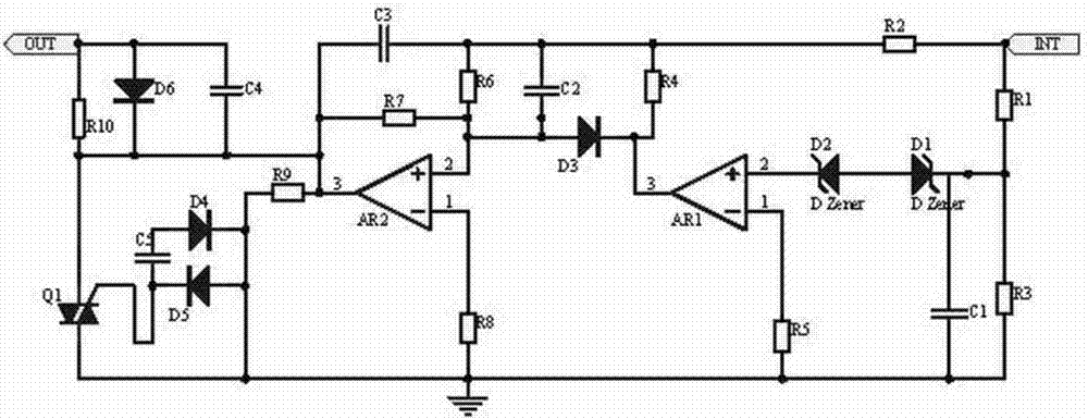
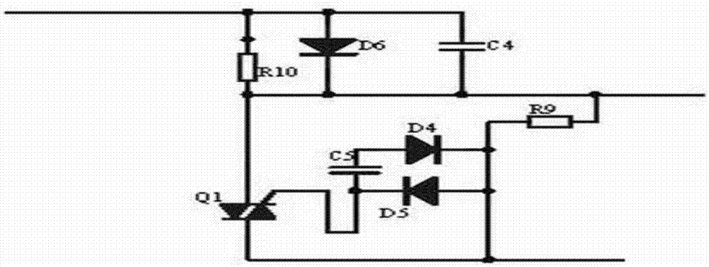
[0015] Embodiment 1, a high-speed multi-channel signal acquisition circuit, including a filter circuit and a rectifier circuit, the filter circuit is connected in series with an RC circuit to filter out medium and high-frequency clutter, and at the same time, the voltage is stabilized and proportionally amplified by an operational amplifier and then input to the rectifier circuit to rectify The circuit uses thyristors and triacs to output stable signals;
[0016] The rectifier circuit adopts the negative electrode of the thyristor D4 to receive the signal of the filter circuit, connects the capacitor C4 in series, uses the characteristics of the capacitor C4 to pass through and block the DC signal to filter out the DC signal in the AC signal, and the other end of the capacitor C4 is connected to the negative electrode of the thyristor D5 and three The control electrode of the terminal thyristor Q1, and the thyristor D5 plays the role of protecting the circuit. If the potential ...
Embodiment 2
[0017] Embodiment 2. On the basis of Embodiment 1, the filter circuit uses resistors R1, R2 and R3 to divide the voltage. Since the signal input port receives a high-frequency signal, it can be filtered by the RC circuit after the voltage division process to achieve the filter. In addition to the effect of medium and high frequency harmonics, in order to protect the circuit, diodes D1~D3 are designed to protect the circuit. In order to ensure that the frequency and amplitude of the signal remain unchanged, op amps AR1 and AR2 are designed to amplify the ratio to maintain the frequency and amplitude of the signal. The value remains unchanged; the filter circuit includes a resistor R1, one end of the resistor R1 is connected to one end of the resistor R3 and the signal input port, the other end of the resistor R1 is connected to the resistor R2, one end of the capacitor C1 and the cathode of the diode D1, and the anode of the diode D1 is connected to The positive pole of the diod...
PUM
 Abstract
Description
Claims
Application Information
 - R&D
- Intellectual Property
- Life Sciences
- Materials
- Tech Scout
- Unparalleled Data Quality
- Higher Quality Content
- 60% Fewer Hallucinations
Browse by: Latest US Patents, China's latest patents, Technical Efficacy Thesaurus, Application Domain, Technology Topic, Popular Technical Reports.
© 2025 PatSnap. All rights reserved.Legal|Privacy policy|Modern Slavery Act Transparency Statement|Sitemap|About US| Contact US: help@patsnap.com


