
A Magnetically Delayed Pseudo-Spark Switch for Pulse Power

A spark switch, pulse power technology, applied in the field of magnetic delay spark switch for pulse power, can solve the problems of anode ablation, large conduction loss, switch heating, etc., and achieve low electrode ablation rate, large current rise rate, low The effect of conduction loss

Active Publication Date: 2019-01-15
XI AN JIAOTONG UNIV
View PDF4 Cites 0 Cited by
  • Summary
  • Abstract
  • Description
  • Claims
  • Application Information

AI Technical Summary

Problems solved by technology

In the specific application, it was found that there are still many problems to be solved in the high repetition frequency pseudo-spark switch, such as large conduction loss, which leads to heat generation of the switch, limitation of repetition frequency working time, life and stability; serious anode ablation, which affects the entire life Discharge stability during the process; insulation recovery speed needs to be further improved, etc.

Method used


Image

  • A Magnetically Delayed Pseudo-Spark Switch for Pulse Power
  • A Magnetically Delayed Pseudo-Spark Switch for Pulse Power
  • A Magnetically Delayed Pseudo-Spark Switch for Pulse Power

Examples


Embodiment Construction

[0020] The structural principle and working principle of the present invention will be further described in detail below in conjunction with the accompanying drawings.

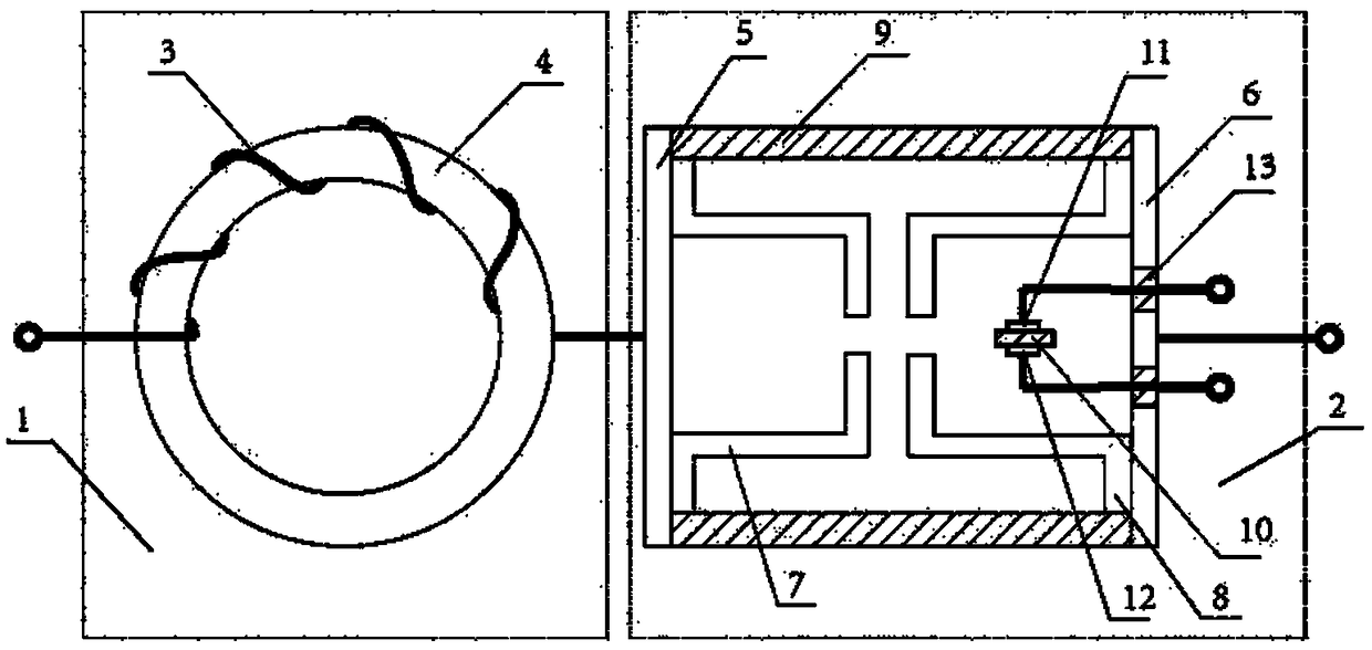
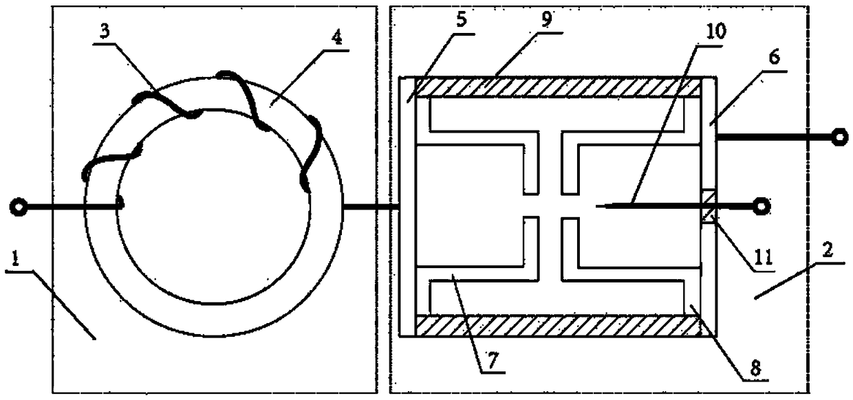
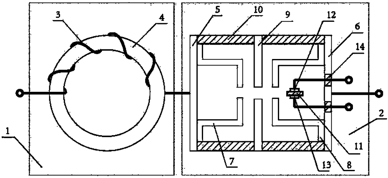
[0021] In one embodiment, the present disclosure discloses a magnetic delay pseudo spark switch for pulse power, including a magnetic switch (1) and a pseudo spark switch (2);

[0022] The magnetic switch (1) is used to delay the rise time of the current;

[0023] The pseudo spark switch (2) is used to undertake the high voltage of pulse discharge;

[0024] The magnetic switch (1) includes a high-voltage insulated wire (3) and a ring magnetic core (4);

[0025] The high-voltage insulated wire (3) is wound on the toroidal core (4);

[0026] The pseudo spark switch (2) includes an anode cover plate (5), a cathode cover plate (6), a hollow anode (7), a hollow cathode (8), an insulating housing (9) and a trigger unit (11);

[0027] The anode cover plate (5), the cathode cover plate (6) and the insulating shell (9) constitute ...


PUM


Abstract

The invention reveals a magnetic-delay pseudo-spark switch for impulse power, and the switch comprises a pseudo-spark switch and a magnetic switch. The magnetic switch is connected to an anode of the pseudo-spark switch in a series manner, and is formed by the winding of a plurality of turns of conductors around a nanocrystalline or ferrite annular magnetic core. The pseudo-spark switch consists of an insulating housing, a hollow cathode, a hollow anode, and a triggering electrode. Moreover, the internal pressure of a closed cavity which consists of the insulating housing and a cover plate of the hollow cathode and the hollow anode is 1-100 Pa. The opposite end faces of the hollow cathode and the hollow anode are provided with a plurality of circular holes, and the diameters of the holes and the distance between two end faces are respectively 3-5mm. The triggering electrode is arranged in the cavity of the hollow cathode, and the discharge mode is a pseudo-spark discharge mode. Only if voltage-second product parameter of the magnetic switch enables the voltage of the pseudo-spark switch to drop to a very low value, can a current flow in an extensive manner. The magnetic delay effect greatly reduces the conduction loss and electronic energy of the pseudo-spark switch, reduces the anode ablation and speeds up the rising of the current.

Description

Technical field [0001] The present disclosure belongs to the fields of pulse power technology, gas lasers, extreme ultraviolet lithography power supplies and the like, and particularly relates to a magnetic delay spark switch for pulse power. Background technique [0002] High-voltage pulse discharge switch is one of the key components of pulse power technology, and it plays an increasingly important role in high-power microwaves, gas lasers, extreme ultraviolet lithography, particle accelerators, etc. Long-term research has been carried out on high-voltage pulse discharge switches at home and abroad. Common forms include high-pressure switches, magnetic switches, solid-state switches, and pseudo-spark switches. But a single device has inherent defects that are difficult to overcome. Compared with the limitations encountered by a single switching device, the magnetic delay switching technology that uses magnetic switches in conjunction with other switches has shown great potenti...

Claims


Application Information

Patent Timeline
Patent Type & Authority Patents(China)
IPC IPC(8): H01T1/22H01T2/02
CPCH01T1/22H01T2/02
Inventor 丁卫东闫家启程乐王亚楠申赛康李志闯
Owner XI AN JIAOTONG UNIV
Learn More