High-voltage direct-current cable outdoor terminal

A high-voltage direct current and cable technology, which is applied to the installation of cable terminals, cable accessories, and cables, can solve the problems of pollution flashover, high electric field strength of insulating bushings, and potential safety hazards, so as to reduce the probability of pollution accumulation and avoid Pollution flashover or breakdown, the effect of uniform electric field intensity distribution

Inactive Publication Date: 2017-11-07
SHOWA TBEA SHANDONG CABLE ACCESSORIES
View PDF5 Cites 0 Cited by
  • Summary
  • Abstract
  • Description
  • Claims
  • Application Information

AI Technical Summary

Problems solved by technology

[0003] At present, my country has invested huge efforts in the development of high-voltage DC cables, and my country's DC cable manufacturing technology has developed rapidly. However, the development of DC cable accessories, especially the outdoor terminals of DC cables with a large amount of consumption, is relatively lagging behind, which has seriously restricted the development of my country's high-voltage DC power system.
The existing high-voltage DC cable outdoor terminals have many shortcomings. For example, the stress cone is generally made of rubber, and the insulating filler is generally silicone oil or polyisobutylene oil. If the stress cone is immersed in the insulating filler for a long time, it is easy to cause damage to the stress cone material. Aging, reducing electrical performance, long-term operation can easily cause insulation damage, and there are potential safety hazards; there are defects in the structural design, and the electric field strength of the external insulating bushing is large, which is prone to pollution accumulation, causing pollution flashover or even breakdown, and poor sealing, which affects the cable safe operation of the system

Method used


Image

  • High-voltage direct-current cable outdoor terminal
  • High-voltage direct-current cable outdoor terminal

Examples


Embodiment 1

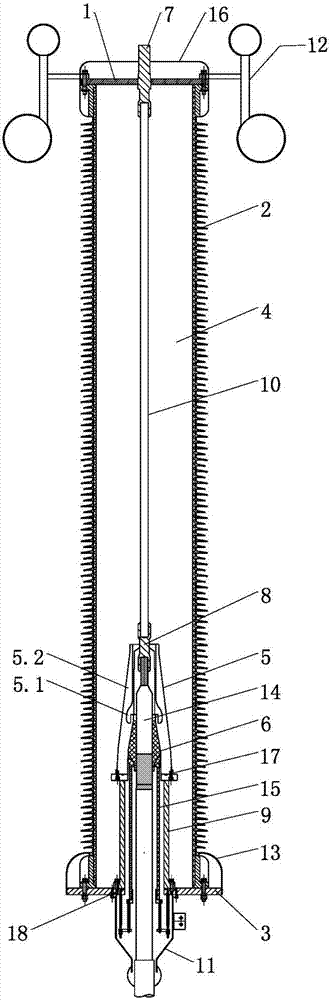
[0033] A high-voltage DC cable outdoor terminal, such as figure 1 As shown, it includes upper flange 1, insulating sleeve 2, lower flange 3, insulating filler 4, cable 14, lower conductor lead-out rod 8, connecting conductor 10, upper conductor lead-out rod 7, stress cone 6, insulating sleeve 2 is a hollow cylindrical structure, the upper end surface and the lower end surface of the insulating sleeve 2 are respectively connected with the lower end surface of the upper flange 1 and the upper end surface of the lower flange 3 to form a sealed chamber 1, which is filled with insulating filler Agent 4, the inner bottom of sealed chamber 1 is provided with sealed chamber 2, the connecting conductor 10 is arranged in sealed chamber 1, the lower end surface of connecting conductor 10 is connected to the top of sealed chamber 2 through the lower conductor lead-out rod 8, and the lower conductor lead-out rod 8 extends To the inside of the sealed chamber 2, the upper end surface of the ...

Embodiment 2

[0036] According to the outdoor terminal of a high-voltage DC cable described in Embodiment 1, the difference is that:

[0037] The sealed chamber 2 includes an inner insulating sleeve 5 and a connecting seat 9. The connecting seat 9 is a hollow cylindrical structure. The end face is connected to the upper end face of the connecting seat 9, the lower end face of the connecting seat 6 is connected to the lower flange 3, and the inner insulating sleeve 5 is provided with an internal shielding electrode 5.1, which is a hollow cylindrical structure.

[0038] The advantage of the design here is that the internal shielding electrode 5.1 provided inside the internal insulating sleeve 5 can even out the electric field distribution in the adjacent parts, so that the electric field intensity of the stress cone 6, the internal insulating sleeve 5, the insulating filler 4, and the insulating sleeve 2 is uniform The distribution reduces the electric field intensity on the surface of the in...

Embodiment 3

[0043] According to the outdoor terminal of a high-voltage DC cable described in Embodiment 1, the difference is that:

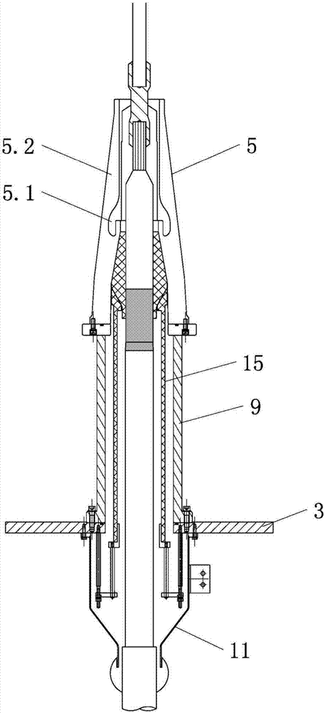
[0044]The outdoor terminal of the high-voltage DC cable also includes a tailpipe 11 and a compression device 15. The lower part of the stress cone 6 is provided with a compression device 15. The bottom of the lower flange 3 is connected to the tailpipe 11. The inner insulating sleeve 5, the connecting seat 9 and the tailpipe 11 form a seal. room two, such as figure 2 As shown, the cable 14 passes through the tail pipe 11 and enters the sealed chamber two.

[0045] The advantage of the design here is that the uniform compressive force applied on the stress cone 6 by the compression device 15 increases the surface pressure strength between the stress cone 6 and the cable 14, reduces the air gap at the interface between the stress cone 6 and the cable 14, The generation of partial discharge is reduced, and the electrical stability of the outdoor terminal is f...


PUM


Abstract

The invention relates to an outdoor terminal of a high-voltage direct current cable, comprising upper fittings, insulating sleeves, lower fittings, insulating fillers, cables, lower conductor lead-out rods, connecting conductors, upper conductor lead-out rods, stress cones, insulating sleeves, and upper fittings . The lower fittings form a sealed chamber 1, which is filled with an insulating filler. The inner bottom of the sealed chamber 1 is provided with a sealed chamber 2. The lower end surface of the connecting conductor is connected to the top of the sealed chamber 2 through the lower conductor lead-out rod, and the lower conductor lead-out rod extends to In the second sealed chamber, the upper end surface of the connecting conductor is connected to the upper conductor lead-out rod, and the upper conductor lead-out rod passes through the upper fitting and protrudes; the cable passes through the lower fitting and extends into the second sealed chamber, and is connected to the lower conductor lead-out rod, and the cable is close to the lower part Part of the conductor lead-out rod is sheathed with a stress cone. The stress cone is set in the second sealing chamber, which effectively isolates the contact between the stress cone and the insulating filler, avoids the aging of the stress cone material caused by the contact, and realizes long-term operation with high stability.

Description

technical field [0001] The invention relates to an outdoor terminal of a high-voltage direct current cable, belonging to the technical field of high-voltage direct current power systems. Background technique [0002] my country is rich in secondary energy resources such as wind energy, solar energy, and tidal energy, and the best transmission method for generating electric energy from such energy is to use flexible high-voltage direct current transmission, because high-voltage direct current cables not only have twice the transmission capacity of AC cables, but also transmit electric energy The loss is only 40% of the AC cable, so the power transmission distance can be greatly extended. The outdoor terminal is an important connector at the end of the transmission and distribution line. It plays an important role in improving the electric field distribution at the end of the DC cable and connecting the cable with other power transmission and transformation equipment. [0003...

Claims


Application Information

Patent Timeline
IPC IPC(8): H02G15/04
CPCH02G15/046
Inventor 陈猛猛王菲赵玉凯住本勉
Owner SHOWA TBEA SHANDONG CABLE ACCESSORIES
Why Eureka
Try Eureka