Fastening structure for split stator iron core

A stator core and fastening structure technology, applied in the direction of magnetic circuit shape/style/structure, manufacturing stator/rotor body, manufacturing motor generator, etc., can solve the problems of low material utilization rate, inability to assemble, motor noise, etc. , to achieve the effect of reducing mold investment cost, convenient operation and size reduction

Pending Publication Date: 2017-11-07
GUANGDONG HEPU POWER TECH
View PDF7 Cites 12 Cited by
  • Summary
  • Abstract
  • Description
  • Claims
  • Application Information

AI Technical Summary

Problems solved by technology

[0005] 3. It can improve the utilization rate of materials, because most of the conventional punching is processed by integral stamping and blanking, and the utilization rate of materials is not high
Therefore, many motor factories are trying to adopt split-type motor punching. For example, Chinese patent CN 205195442 U introduces a stator core with a split structure. Connection, this structure can improve slot fullness, motor efficiency, and material utilization. However, the problem with this structure is that if the tenon and tenon are too loose, the motor will generate noise and vibration. If it is too tight, the motor will not be able to Assembling, the Chinese patent CN 205911842 U introduces a split-type inner stator core discharge processing method, which does not solve the technical problems existing in the structure

Method used


Image

  • Fastening structure for split stator iron core
  • Fastening structure for split stator iron core
  • Fastening structure for split stator iron core

Examples


Embodiment 1

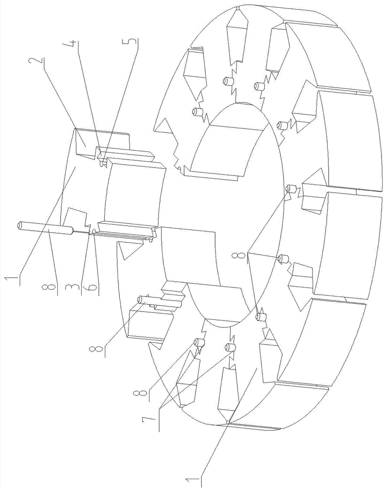
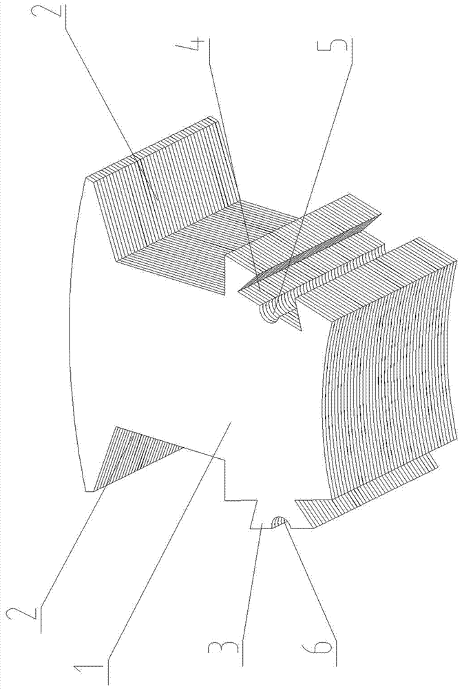
[0021] Embodiment 1: As shown in the figure, the present invention includes several fan-shaped core units 1 connected in series to each other to form a ring-shaped stator core. The upper parts of the fan-shaped core units 1 are provided with grooves 2, and the fan-shaped core units 1 The lower parts of both sides are provided with dovetail-shaped tenons 3 and dovetail-shaped tenon grooves 4 respectively. Two adjacent fan-shaped iron core units 1 are connected by the tenons 3 and tenon grooves 4 embedded together. The two adjacent fan-shaped iron core units 1 The grooves 2 are butted to form a slot for winding the stator coil. The fan-shaped core unit 1 is composed of several laminated punches. The notches 6 and 5, the columnar notch 6 of the tenon 3 and the columnar notch 5 of the tenon groove 4 connect to form a cylindrical hole 7, and a cylindrical wedge 8 is embedded in the columnar hole 7 for interference.

[0022] The cross-section of the columnar hole is one of circular,...

Embodiment 2

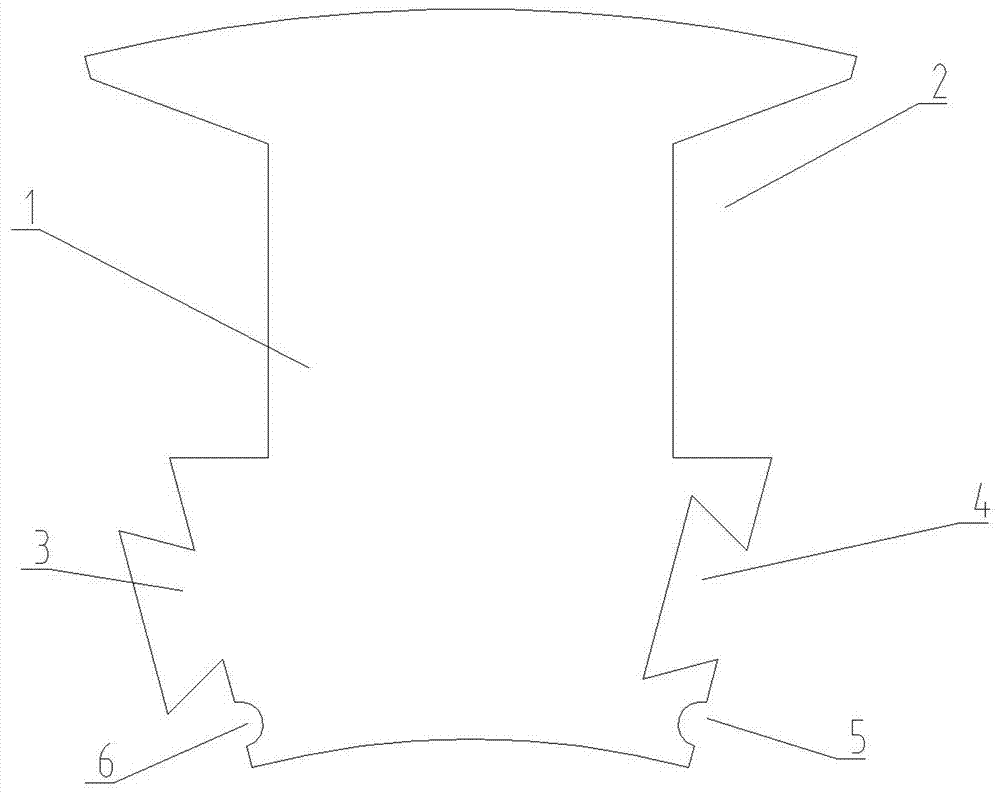
[0023] Embodiment 2: as image 3 As shown, the semicircular columnar notches 6 and 5 are respectively provided on the connecting surfaces of two adjacent fan-shaped iron core units 1 except the tenon 3 and the tenon groove 4 .


PUM


Abstract

A fastening structure for a split stator iron core comprises a plurality of fan-shaped iron core units which are connected in series to form an annular stator core. Grooves are arranged in the upper two sides of each fan-shaped iron core unit, and a tenon and a mortise are respectively arranged on the two lower sides of the fan-shaped iron core unit. Two adjacent fan-shaped iron core units are connected together through tenons and mortises embedded together, and the grooves of the two adjacent fan-shaped iron core units are in abut joint to form a wire duct for winding stator coils. Each fan-shaped iron core unit is formed by punching sheets laminated together. Cylindrical gaps are formed on the connecting surfaces of the tenons and the mortises, the cylindrical gaps of the tenons and the mortises form a cylindrical hole after connection, and a wedge is embedded in the cylindrical hole in an interference fit manner. Compared with the prior art, the fastening structure is convenient for assembly, realizes fastening connection of the split stator iron core after assembly, and prevents unreliable work of a motor due to loosening of the split stator iron core.

Description

technical field [0001] The invention relates to the technical field of motors. . Background technique [0002] The advantages of the split stator core are obvious. For the motor with concentrated winding, it has the following advantages: [0003] 1. It can increase the full rate of the motor slot, which can reach more than 90%; [0004] 2. It can reduce the size of the punching die and reduce the investment cost of the die; [0005] 3. It can improve the utilization rate of materials, because most of the conventional stamping sheets are processed by integral punching and blanking, and the utilization rate of materials is not high. Therefore, many motor factories are trying to adopt split-type motor punching. For example, Chinese patent CN 205195442 U introduces a stator core with a split structure. Connection, this structure can improve slot fullness, motor efficiency, and material utilization. However, the problem with this structure is that if the tenon and tenon are t...

Claims


Application Information

Patent Timeline
Patent Type & Authority Applications(China)
IPC IPC(8): H02K1/14H02K15/02
CPCH02K1/14H02K15/022H02K2201/15
Inventor 梁昌勇
Owner GUANGDONG HEPU POWER TECH
Why Eureka
Try Eureka