
A moving component used for a detection device and a detection device having the same

A detection device and component technology, applied in the field of medical devices, can solve problems such as lack of data support, inability to realize the function of the stapler detection device, tearing of the patient, etc., and achieve the effect of small power loss

Active Publication Date: 2020-04-24
FENGH MEDICAL CO LTD
View PDF5 Cites 0 Cited by
  • Summary
  • Abstract
  • Description
  • Claims
  • Application Information

AI Technical Summary

Problems solved by technology

Due to the internal structural design of the existing stapler, the next effective firing can only be performed when the firing handle and the positioning handle cannot be moved each time. The insufficient firing force applied by the operator will make the firing handle not fully connected with the positioning handle. Abutting thus affecting the normal use of the stapler
In this case, it can only be fired again, and because the patient's tissue is clamped in the end effector of the stapler, firing again will cause accidental injuries such as tearing to the patient, affecting the normal operation
Therefore, it is necessary to detect the firing force of the stapler, and the detection of the firing force of the stapler in the prior art can only rely on the feel of the inspector, there is no effective device for detecting the firing force of the stapler, and there is no objective data support
However, there is no moving component suitable for the stapler detection device in the prior art, and the function of the stapler detection device cannot be realized.

Method used


Image

  • A moving component used for a detection device and a detection device having the same
  • A moving component used for a detection device and a detection device having the same
  • A moving component used for a detection device and a detection device having the same

Examples


Embodiment Construction

[0025] Embodiments of the invention are described in detail below, examples of which are illustrated in the accompanying drawings. In describing the present invention, it should be understood that the terms "center", "longitudinal", "transverse", "length", "width", "thickness", "upper", "lower", "front", " Back", "Left", "Right", "Vertical", "Horizontal", "Top", "Bottom", "Inner", "Outer", "Clockwise", "Counterclockwise", "Axial", The orientation or positional relationship indicated by "radial", "circumferential", etc. is based on the orientation or positional relationship shown in the drawings, and is only for the convenience of describing the present invention and simplifying the description, rather than indicating or implying the referred device or element Must be in a particular orientation, be constructed in a particular orientation, and operate in a particular orientation, and therefore should not be construed as limiting the invention.

[0026] In addition, the terms "...


PUM


Abstract

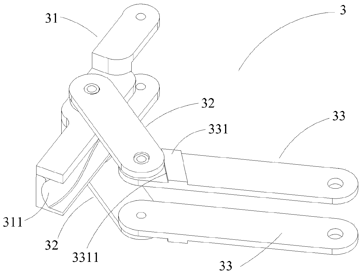
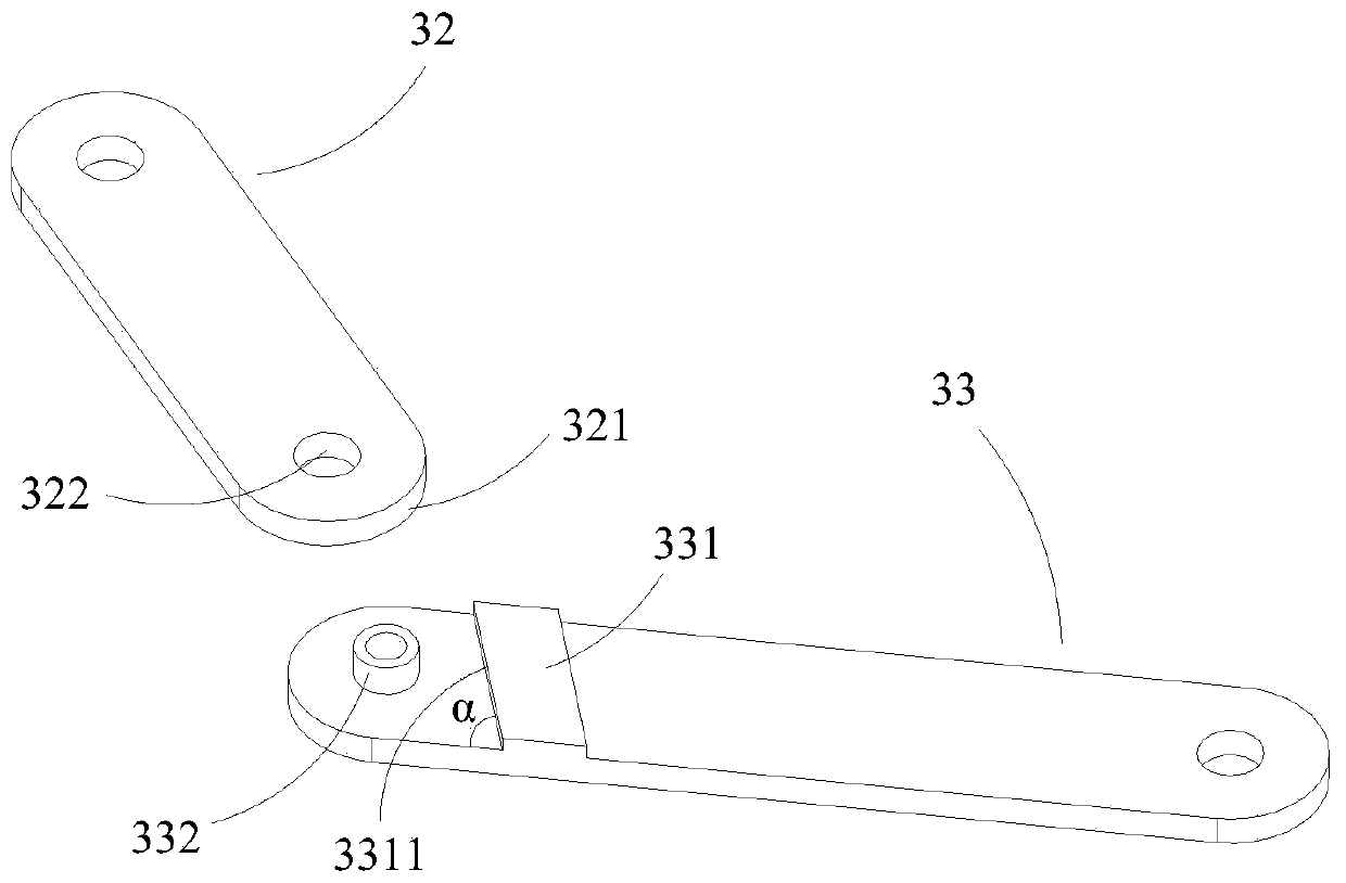
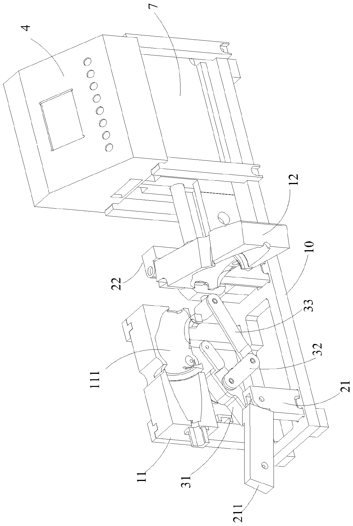
The invention discloses a motion component for a detecting device. The motion component comprises a first connecting rod, a second connecting rod and a third connecting rod, wherein the motion component is used for converting linear motion into arc-shaped motion; any one of the second connecting rod and the third connecting rod is provided with a limiting structure, and the limiting structure is matched with the other one of the second connecting rod and the third connecting rod, and is used for limiting the rotating angle of the motion component, so that the stroke of the motion component is guaranteed, and further, a detected object is completely separated from the motion component. According to the motion component for the detecting device and the detecting device provided with the motion component, in the transmission process of force, the power loss is small, a detection force value can be effectively transmitted, the firing force is detected, a detection value is digitally displayed, and thus data support is provided for the improvement of the performance improvement of the firing force of an anastomat.

Description

technical field [0001] The invention relates to a detection device of a surgical instrument, in particular to a moving component used for the detection device and a detection device with the detection device, belonging to the field of medical devices. Background technique [0002] The stapler and its executive components suitable for surgical operations are surgical instruments that can remove excess tissue while suturing the patient's wound. It is widely used in minimally invasive surgery such as abdominal surgery, gynecology, pediatrics, and thoracic surgery. Excision and anastomosis. The operation carried out under the endoscope generally only needs to open several small holes on the patient's body, and excision, suturing tissue and auxiliary instruments are inserted into the patient's body through the small holes for surgery. Minimally invasive surgery brings little trauma to patients, and patients can recover in a short period of time. Therefore, minimally invasive sur...

Claims


Application Information

Patent Timeline
Patent Type & Authority Patents(China)
IPC IPC(8): A61B90/00A61B17/072A61B17/00
CPCA61B17/00234A61B17/07207A61B2017/00398
Inventor 孙宝峰马猛王大全
Owner FENGH MEDICAL CO LTD
Learn More