
Train integrity checking system based on wireless communication, satellite navigation and inertial navigation

A technology for integrity inspection and satellite navigation, applied in signal transmission systems, railway signals, transportation and packaging, etc., can solve problems such as inability to adapt to non-penetrating train buses, inability to obtain train length data, and increase interface complexity, and improve the System reliability, reduced maintenance workload, and the effect of reducing trackside equipment

Pending Publication Date: 2017-11-10
SIGNAL & COMM RES INST OF CHINA ACAD OF RAILWAY SCI +4
View PDF2 Cites 7 Cited by
  • Summary
  • Abstract
  • Description
  • Claims
  • Application Information

AI Technical Summary

Problems solved by technology

[0007] However, for the above method 1, a large amount of equipment needs to be installed beside the track, the construction cost is high, installation and maintenance are difficult, and both the track circuit and the axle counting are inevitably vulnerable to interference
Especially the track circuit method widely used at present, there are problems of red light band and undead
For the above method 2, wind pressure monitoring equipment needs to be installed at the rear of the train. This device needs to be connected to the brake air duct of the existing vehicle, which increases the complexity of the interface, easily introduces new risk points, and cannot obtain the length data of the train.
For the above method 3, the train is required to have a train bus that runs through the head and tail, and there are special requirements for the vehicle, which cannot be adapted to the situation where there is no through train bus such as freight trains, and the scope of application is limited.

Method used


Image

  • Train integrity checking system based on wireless communication, satellite navigation and inertial navigation
  • Train integrity checking system based on wireless communication, satellite navigation and inertial navigation

Examples


Embodiment Construction

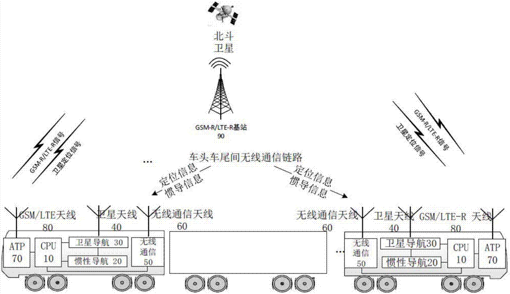
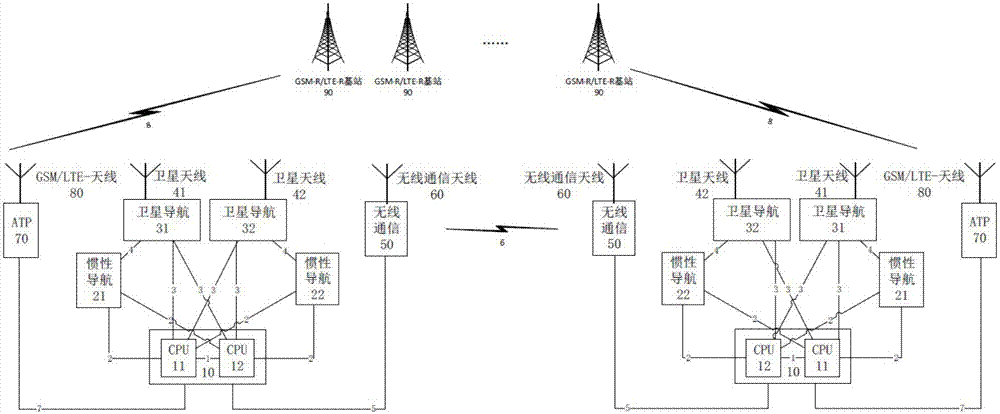
[0032] Attached below Figure 1-2 The train integrity inspection system and inspection method based on wireless communication, satellite navigation and inertial navigation of the present invention are described in detail.

[0033] Such as figure 1 As shown, the train integrity inspection system based on wireless communication, satellite navigation and inertial navigation includes: a train head positioning unit and a train tail positioning unit; the train head positioning unit includes: the first automatic train protection system 70, the first CPU 10, The first satellite navigation device 30, the first inertial navigation device 20 and the first wireless communication device 50; The wireless communication device 50 carries out communication connection; The train tail positioning unit comprises: the second automatic train protection system 70, the second CPU10, the second satellite navigation device 30, the second inertial navigation device 20 and the second wireless communicat...


PUM


Abstract

The invention provides a train integrity checking system based on wireless communication, satellite navigation and inertial navigation. The train integrity checking system comprises a train head positioning unit and a train tail positioning unit. The train head positioning unit comprises a first automatic train defense system, a first CPU, a first satellite navigation device, a first inertial navigation device and a first wireless communication device. The first CPU is connected with the first automatic train defense system, the first satellite navigation device, the first inertial navigation device and the first wireless communication device in a communication manner. The train tail positioning unit comprises a second automatic train defense system, a second CPU, a second satellite navigation device, a second inertial navigation device and a second wireless communication device. The second CPU is connected with the second automatic train defense system, the second satellite navigation device, the second inertial navigation device and the second wireless communication device in a communication manner. The first satellite navigation device and the second satellite navigation device are used for acquiring the position data of the two ends of a train.

Description

technical field [0001] The invention belongs to the technical field of railway signals, in particular to a train integrity inspection system based on wireless communication, satellite navigation and inertial navigation. Background technique [0002] The railway signal system is responsible for controlling the operation of trains on the line. Usually, methods such as time separation or space separation are used to ensure that the trains maintain a fixed or variable interval between each other and realize the tracking operation of the trains. In the above control, it is necessary to obtain the length of the train and track the integrity of the train in real time, so as to avoid the occurrence of train collision accidents due to the wrong train length or the loss of integrity of the train. [0003] In the prior art, the integrity check of railway trains mainly has the following methods: [0004] 1. Based on the track circuit or axle counting equipment installed beside the trac...

Claims


Application Information

Patent Timeline
Patent Type & Authority Applications(China)
IPC IPC(8): B61L15/00G08C17/02
CPCB61L15/0027B61L15/0054
Inventor 施卫忠朱少彤杨志杰开祥宝李克欧阳籽勃
Owner SIGNAL & COMM RES INST OF CHINA ACAD OF RAILWAY SCI
Learn More