
Smelting system for metal

A metal and smelting furnace technology, applied in furnace cooling, waste heat treatment, charge manipulation, etc., can solve the problems of reduced surface quality of ingots, influence of surrounding environment, uneven cooling, etc., to achieve simple and reasonable shape and structure, and time-consuming maintenance. short, the effect of improving the production environment

Pending Publication Date: 2017-11-10
熊曙雄
View PDF7 Cites 0 Cited by
  • Summary
  • Abstract
  • Description
  • Claims
  • Application Information

AI Technical Summary

Problems solved by technology

Such as the existing metal smelting furnace due to the shape and structure of the furnace body cavity, such as the shape of the bottom wall is a reverse trapezoid, which is not only inconvenient to clean the slag, but also takes a long time, and it is laborious and difficult to clean the slag. clean, affect production efficiency
Moreover, due to its internal and external structure, the slag removal process also affects the surrounding environment. The metal smelting slag falls all over the ground, and it still burns people, and even punctures the slag-carrying tires.
In addition, due to the high temperature and particularity of metal smelting, it is not easy to install a discharge part with adjustable height. Reasonable, and there is a contradiction between the discharge of the smelting liquid and the immersion elevation and the slag cleaning of the furnace chamber, which cannot be coordinated with each other
Either it is inconvenient to remove slag, or the height of metal immersion is limited, which affects the effect of immersion smelting, increases energy consumption and reduces production efficiency
[0003] In the smelting and ingot casting system, ring-shaped ingot casting machines are usually used for casting ingots, but the structure of this kind of ingot casting machine is not reasonable, such as the connection structure and corresponding shape of the casting molds. Moreover, the connection is unreliable, prone to loosening, affecting normal production, and even causing safety production accidents due to connection problems during operation.
[0004] In addition, ingot cooling is a basic process of smelting ingots. There are usually two ways for traditional ingot cooling. One is to directly input cooling water into the cooling holes inside the mold to achieve rapid cooling of the castings in the mold. Cooling device and corresponding cooling method Because the cooling speed of the ingot is fast and the cooling is uneven, it is easy to cause serious deformation of the ingot during the cooling process. When the cast ingot parts have a certain precision, the degree of deformation is more affected. At the same time, the cooling water is in direct contact with the casting, which reduces the surface quality of the ingot, which makes the quenching property of the casting, and when ingot a certain metal such as aluminum, the casting will turn black and discolored, etc., resulting in poor quality of the ingot casting
Another way is to spray water for cooling, which also has the problem of uneven cooling and poor cooling effect. At the same time, this cooling device and corresponding cooling method will generate a large amount of water vapor, which will affect the production site and the surrounding production environment. , and the water mist generated by it may also affect the sight of the on-site operators, so that undue operational safety accidents may occur due to improper operation of the operators; and another problem with this cooling method is that it is the same as the first method , which will make certain ingot products black and discolored, affecting the quality of casting products

Method used


Image

  • Smelting system for metal
  • Smelting system for metal
  • Smelting system for metal

Examples


Embodiment Construction

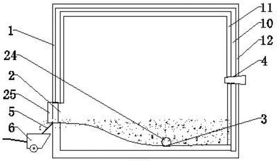
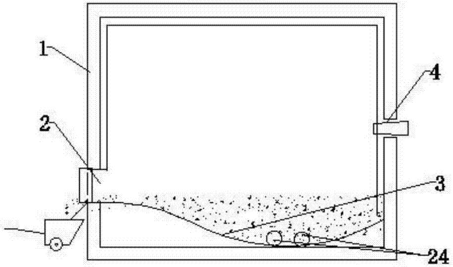
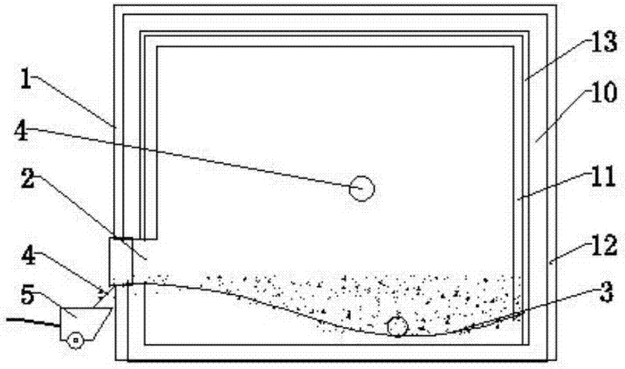
[0012] The present invention will be further described by embodiment now in conjunction with accompanying drawing, as figure 1 shown. The metal smelting system in this example includes a smelting furnace, and the smelting furnace includes a furnace body 1, a soup flow port (or smelting liquid discharge port) 24 and a feed port 2 arranged on the corresponding side (front) of the furnace body 1 And corresponding material door device 25 etc. Its feed port 2 also constitutes the slag removal port of the smelting furnace of the metal smelting system. The furnace body 1 includes a frame layer 10, an insulating layer 12 and an inner layer 11. The insulating layer 12 is arranged on the relative outer side of the frame layer, and the frame layer is made of refractory bricks. Its insulation layer 12 is formed by plastering the surface of the frame layer with refractory mud. The outer wall of the insulation layer 12 is provided with a layer of iron wrapping protective layer. The sett...


PUM


Abstract

The invention discloses a smelting system for metal. The smelting system comprises a smelting furnace, a corresponding casting device, a molten metal flowing port and / or a slag clearing port and a corresponding material door device, wherein the molten metal flowing port and / or a slag clearing port is formed in a smelting furnace body. The smelting furnace body comprises a frame layer and an inner layer and is characterized in that an immerging regulating port is further formed in a furnace cavity of the furnace body, the set height of the immerging regulating port is larger than the set height of the molten metal flowing port and / or slag clearing port, and a leading-out device is arranged corresponding to the molten metal flowing port and / or the slag clearing port. The smelting system for the metal is simple and reasonable in principle structure, can improve the environment of a production site for cast ingot smelting, further can improve production efficiency to a certain degree, clears slag more easily and conveniently, and lowers labor intensity; meanwhile, the smelting system has a better smelting effect and higher smelting efficiency, and is good in adaptability and high in serviceability.

Description

technical field [0001] The invention relates to a smelting system, in particular to a metal smelting system. Background technique [0002] In the metal regeneration smelting ingot casting system, the shape and structural composition of the metal smelting furnace not only directly affect the operating efficiency of the smelting system, fuel consumption, etc., such as the material fluidity of the metal smelting furnace, the uniformity of furnace chamber pressure and temperature, etc.; Moreover, it also directly affects the operation of the smelting process, such as maintenance and slag removal of metal smelting furnaces, etc. This is more obvious for a single furnace or a multi-furnace combination with an unreasonable structure. Such as the existing metal smelting furnace due to the shape and structure of the furnace body cavity, such as the shape of the bottom wall is a reverse trapezoid, which is not only inconvenient to clean the slag, but also takes a long time, and it is ...

Claims


Application Information

Patent Timeline
Patent Type & Authority Applications(China)
IPC IPC(8): F27D1/10F27D1/18F27D3/15F27D9/00F27D17/00B22D30/00
CPCF27D1/10F27D1/1858F27D3/1545F27D9/00F27D17/004B22D30/00F27D2009/0002
Inventor 熊曙雄刁晓华简玉平熊曙海陈敬福徐忠清朱玉亮
Owner 熊曙雄
Learn More