Electric heating roller furnace structure optimization method

An optimization method and technology of electric heating rollers, applied in design optimization/simulation, electrical digital data processing, special data processing applications, etc., can solve the problems of long optimization design cycle, blind structure adjustment direction, inability to meet, etc., to ensure the furnace temperature The effect of uniformity, shortening the structure optimization cycle and saving design cost

Inactive Publication Date: 2017-11-10
湖南烁科热工智能装备有限公司
View PDF7 Cites 7 Cited by
  • Summary
  • Abstract
  • Description
  • Claims
  • Application Information

AI Technical Summary

Problems solved by technology

Using this electric roller furnace structure optimization method, the time and capital costs are high, the direction of structural adjustment is blind, lack of sufficient theoretical support, the optimization design cycle is long, and it cannot meet the requirements of the lithium battery material preparation process for sintering equipment

Method used


Image

  • Electric heating roller furnace structure optimization method
  • Electric heating roller furnace structure optimization method
  • Electric heating roller furnace structure optimization method

Examples


Embodiment 1

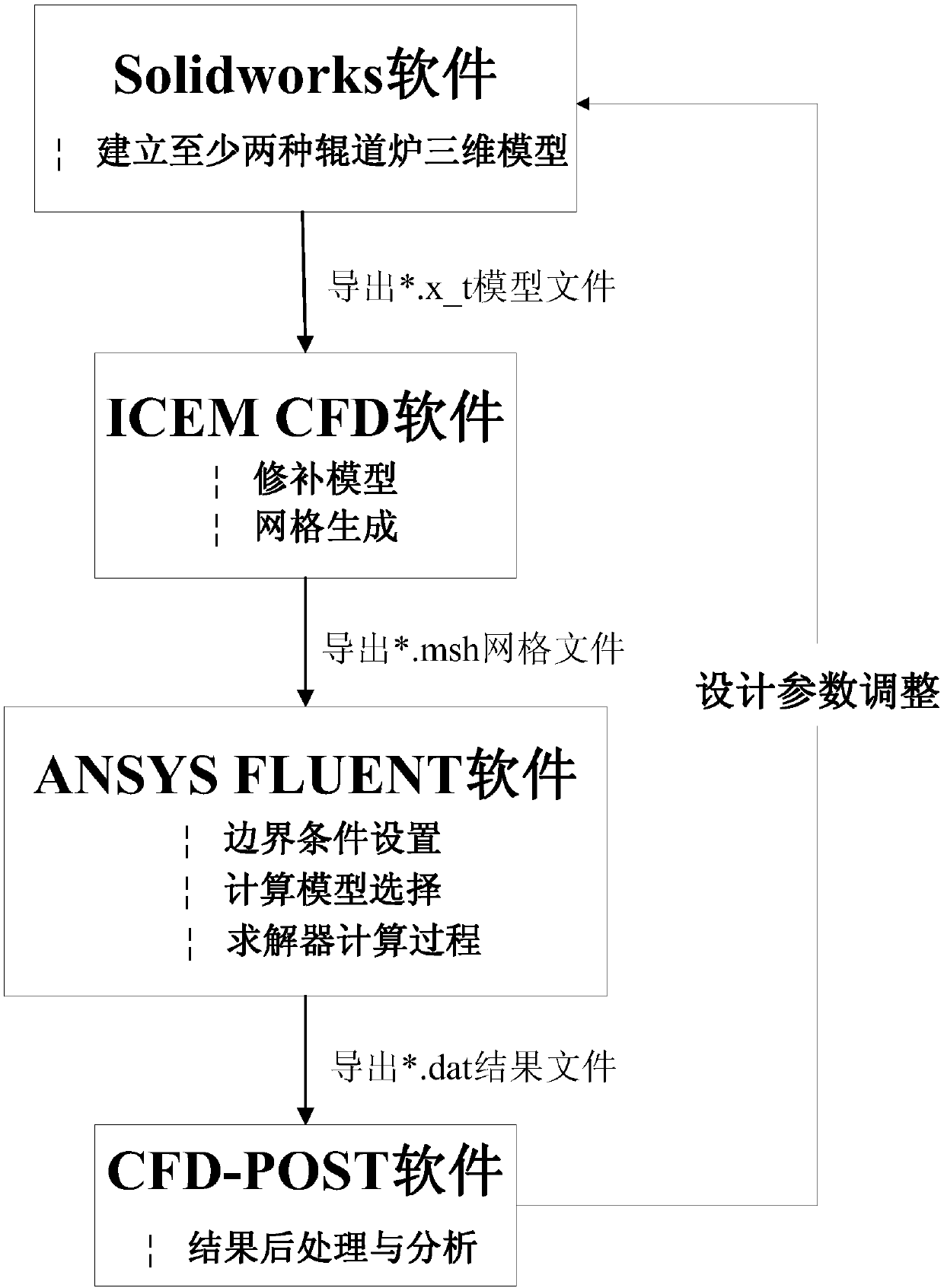
[0039] In step S01, the structural optimization of the electrothermal roller furnace is realized by adjusting the furnace width-to-height ratio in the design parameters, specifically: two types of roller furnace models are established, and the furnace width-to-height ratio of the original structure model is: 2:1 , while the furnace width-to-height ratio of the new model 1 is 1.5:1, and other design parameters such as the furnace width-to-height ratio are the same. Execute steps S02 to S04. In step S04, the dimensionless temperature difference coefficients of the hearth center section of the two roller furnace models are obtained As shown in Table 1 below:

[0040] Table 1:

[0041] Model

[0042] According to the comparison results, the new model with a smaller temperature difference coefficient is taken as the optimal solution, and then the furnace width-to-height ratio is adjusted at least once for the optimal solution, and then steps S02 to S04 are repeated to c...

Embodiment 2

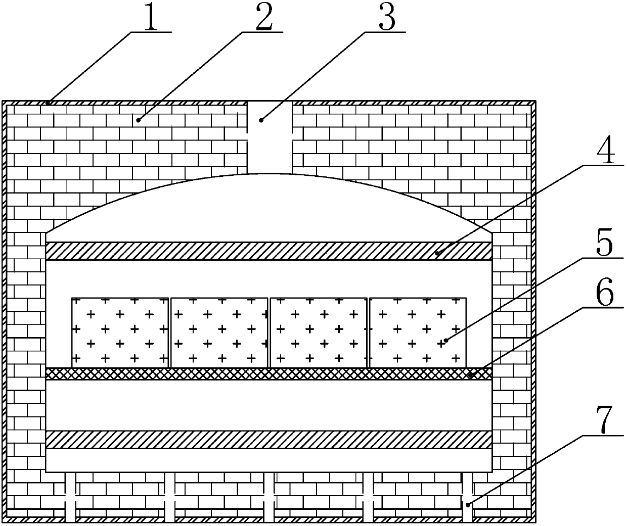
[0044] The difference between this embodiment and the first embodiment is that the structural optimization of the electric roller furnace is realized by adjusting the spacing of the silicon carbide rods in the design parameters, and other design parameters such as the width and height of the furnace are not adjusted.

[0045] Specifically, in step S01, three types of roller hearth furnace models are established, wherein the distance between the SiC rods of the original structure model is 250 mm, the distance between the SiC rods of the new model 2 is 220 mm, and the distance of the SiC rods of the new model 3 is 280 mm. Then execute steps S02-S04. In step S04, calculate the dimensionless temperature difference coefficients of the hearth center sections of the three roller furnace models The calculation results are shown in Table 2 below:

[0046] Table 2:

[0047] Model

SiC rod spacing (mm)

temperature difference coefficient

original structure model

...


PUM


Abstract

The invention discloses an electric heating roller furnace structure optimization method. The method comprises the steps of S01, building multiple roller furnace body models with different design parameters; S02, importing the roller furnace body models into ICEM CFD software, performing model repair and grid division, and importing a grid file generated after the grid division into ANSYS Fluent software; S03, setting material property parameters, calculating boundary conditions and selecting a calculation model in the ANSYS Fluent software, initializing a calculation domain and performing calculation by utilizing a solver; and S04, importing a result file obtained by the in the ANSYS Fluent software into CFD-POST, performing comparative analysis on dimensionless temperature difference coefficients of furnace chamber center sections of the models, and taking the roller furnace body model with the relatively small temperature difference coefficient as an optimal scheme. The electric heating roller furnace structure optimization method has the advantages of low cost, short optimization time and the like.

Description

technical field [0001] The invention mainly relates to the technical field of roller hearth furnaces, in particular to a method for optimizing the structure of electric heating roller hearth furnaces. Background technique [0002] With the rapid development of the new energy industry, the lithium battery industry has become a hot spot today, and the lithium battery material is a key factor determining its performance. The demand for lithium battery materials has increased sharply, and there is an urgent need for efficient large-scale mass production. The electric heating roller furnace is a necessary large-scale continuous sintering equipment in the preparation process of lithium battery materials. With the gradual increase in the market demand for lithium battery materials, manufacturers of lithium battery materials have increased equipment production capacity. The electric heating roller table of sintering equipment The cross-section of the furnace body continues to widen...

Claims


Application Information

Patent Timeline
Patent Type & Authority Applications(China)
IPC IPC(8): G06F17/50
CPCG06F30/20
Inventor 李鹏飞苏文生周时宇王世刚
Owner 湖南烁科热工智能装备有限公司
Why Eureka
Try Eureka