micro light emitting diode display device

A technology of micro-light-emitting diodes and display devices, which is applied to static indicators, instruments, semiconductor devices, etc., can solve problems such as increased power consumption, difficulties, and limited product resolution, and achieve the effects of increasing brightness and improving flexibility

Active Publication Date: 2019-12-31
AU OPTRONICS CORP
View PDF8 Cites 0 Cited by
  • Summary
  • Abstract
  • Description
  • Claims
  • Application Information

AI Technical Summary

Problems solved by technology

However, because organic light emitting diodes are small in size and densely arranged, it is more difficult to apply the traditional process of single-sided printing to micro light emitting diodes to make display devices, and the process of pasting and transposition is limited by the accuracy of the mechanism , The material properties of the stamp and the accuracy of the unit pitch (pitch) limit the resolution of the product, and when one side is pasted in a high-density arrangement, it is easy to generate interference from adjacent micro-LEDs during placement transposed, thus causing misplacing
[0005] Some wearable display devices on the market are affected by the low brightness, which affects the clarity, and the luminous efficiency must be improved to improve. However, when the brightness of organic light-emitting diodes with low efficiency is increased, the power consumption will be increased, while micro-light-emitting diodes Under the same power consumption, the brightness is already much higher than that of organic light-emitting diodes. However, in order to meet the needs of more diverse display devices and take into account the needs of brightness and clarity, it is necessary to actively develop technology to increase brightness to meet the needs.

Method used


Image

  • micro light emitting diode display device
  • micro light emitting diode display device
  • micro light emitting diode display device

Examples


Embodiment Construction

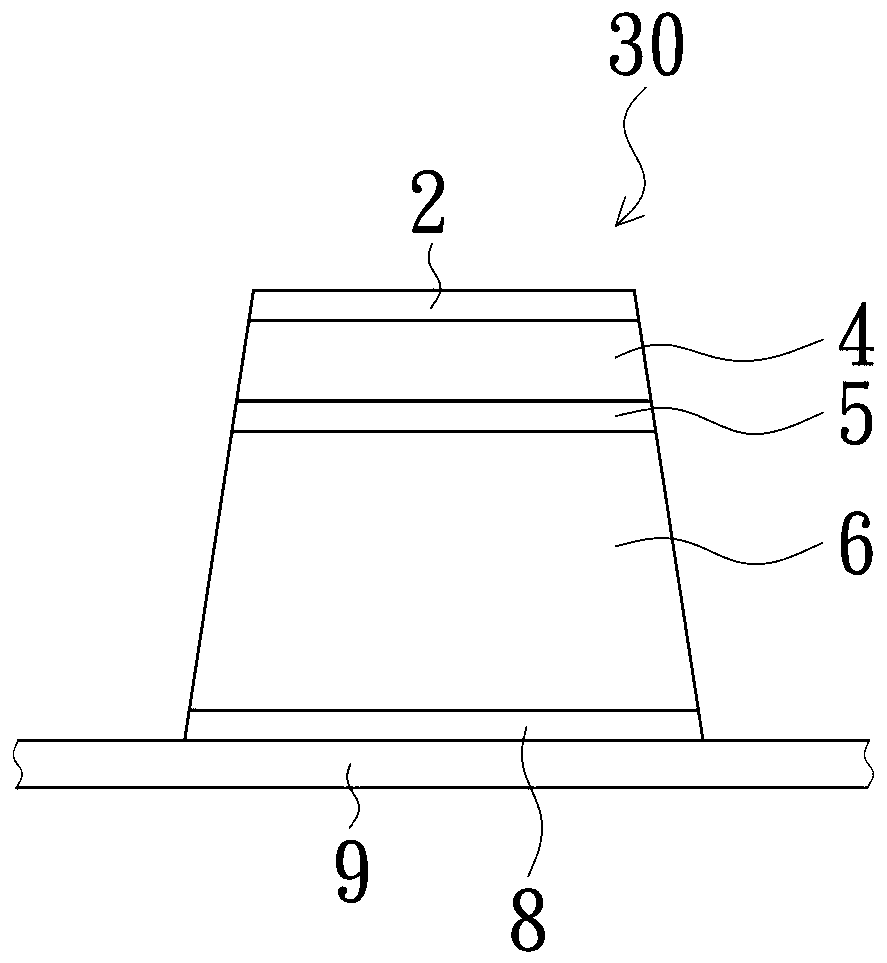
[0058] see figure 1 ,figure 1 A side view of a micro-LED. figure 1 The shown micro light emitting diode 30 can be utilized in the present invention, but the present invention is not limited to this kind of micro light emitting diode 30, the micro light emitting diode 30 includes a first electrode 2, a second electrode 8, a first type semiconductor 4, a second electrode The second-type semiconductor 6 and the light-emitting layer 5, the first electrode 2 and the second electrode 8 respectively give electric energy to the outer ends of the first-type semiconductor 4 and the second-type semiconductor 6 to form a potential difference, which will make the first-type semiconductor 4 and the second-type semiconductor The holes in the light-emitting layer 5 of the second-type semiconductor 6 are combined with electrons, so the energy level is lowered and released in the form of light. The micro light emitting diodes 30 can be disposed on the substrate 9, and the substrate 9 of the pr...


PUM


Abstract

A micro light emitting diode display device includes a first substrate and a second substrate which are oppositely arranged. A plurality of micro light emitting diodes are respectively disposed at adjacent surfaces of the first substrate and the second substrate, whereby the micro light emitting diodes are disposed with high density to improve the resolution. If the first substrate and the second substrate are both flexible substrates, and the above micro light emitting diodes are respectively disposed to the first substrate and the second substrate, thereby improving flexibility of the micro light emitting diode display device. If a reflection cup is disposed corresponding to the micro light emitting diodes, the brightness can be enhanced or the light emitting direction can be changed, thereby forming the micro light emitting diode display device capable of improving brightness and flexibility and increasing the resolution.

Description

technical field [0001] The present invention relates to a display device, in particular to a micro light emitting diode display device. Background technique [0002] Display devices made of organic light-emitting diodes (OLEDs) are actively replacing liquid crystal displays in the smartphone market. At the same time, another display technology, micro-light-emitting diode (Micro LED), is gradually being deployed, and has the opportunity to surpass organic light-emitting diodes, subvert the current display technology situation, and expand higher-level technology applications. [0003] Micro-LED is an array structure of miniaturized light-emitting diodes, which has self-luminous display characteristics. With active components, each pixel can be individually addressed and driven to emit light. The advantages include high brightness, low power consumption, small size, and ultra-high resolution. Rate and color saturation etc. Micro-LEDs and organic light-emitting diodes are suit...

Claims


Application Information

Patent Timeline
Patent Type & Authority Patents(China)
IPC IPC(8): H01L27/15G09G3/32
CPCG09G3/32H01L27/15
Inventor 刘仲展吴宗典陈振彰林宗毅
Owner AU OPTRONICS CORP
Why Eureka
Try Eureka