
Mirror image milling method and system for skin machining

A technology of mirror milling and skinning, used in metal processing, metal processing equipment, metal processing mechanical parts, etc., can solve the problem of difficult to guarantee the wall thickness accuracy of chemical milling, poor contour accuracy, and can not meet the requirements of hyperbolic/single-curved wall panels. Parts processing requirements, etc.

Active Publication Date: 2017-11-14
SHANGHAI TOPNC NUMERICAL CONTROL TECH CO LTD +1
View PDF7 Cites 29 Cited by
  • Summary
  • Abstract
  • Description
  • Claims
  • Application Information

AI Technical Summary

Problems solved by technology

[0003] 1. It is difficult to guarantee the wall thickness accuracy of chemical milling. The thickness accuracy of chemical milling is currently generally ±0.5mm, while the wall thickness of large skins is required to reach ±0.1mm
[0004] 2. The contour accuracy is poor. The contour of the chemical milling area is usually guaranteed by manual engraving, resulting in a low contour accuracy of 2mm, while the large-scale skin contour accuracy requires ±0.3mm
[0005] 3. Many new skins cannot be processed by chemical milling, such as the aluminum-lithium alloy skin of a new aircraft cannot be processed by chemical milling due to material characteristics
[0007] The above-mentioned traditional chemical milling can no longer meet the processing requirements of hyperbolic / single-curved wall plate parts with strict wall thickness requirements such as large skins and similar workpieces.

Method used

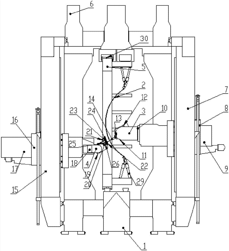
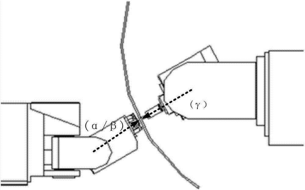

Image

  • Mirror image milling method and system for skin machining
  • Mirror image milling method and system for skin machining
  • Mirror image milling method and system for skin machining

Examples


Embodiment Construction

[0045] The present invention will be described in detail below in conjunction with specific embodiments. The following examples will help those skilled in the art to further understand the present invention, but do not limit the present invention in any form. It should be noted that those skilled in the art can make several changes and improvements without departing from the concept of the present invention. These all belong to the protection scope of the present invention.

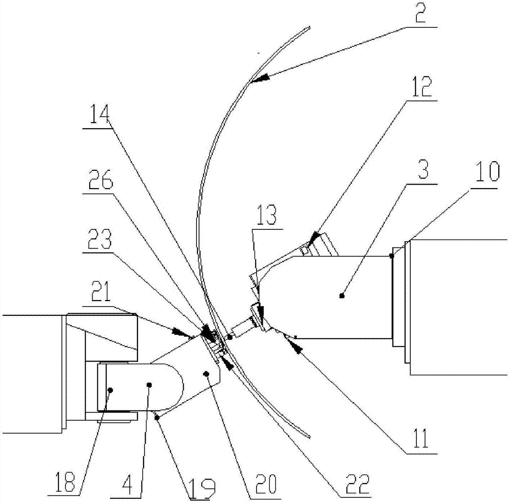
[0046] The invention relates to a mirror image milling method and system for skin processing. In the present invention, a processing tool is arranged on the processing surface of the skin; a group of floating support devices, a skin shape laser scanning device, and a group of skin wall thickness real-time measuring devices are arranged in the symmetrical area of ​​the skin processing surface. Before skin processing, the actual shape of the skin is obtained by using the skin shape laser scanning device, ...


PUM


Abstract

The invention provides a mirror image milling method and system for skin machining. A machining tool is arranged on a machining surface. A set of floating supporting devices, a skin appearance laser scanning device and a set of skin wall thickness real-time measuring devices are arranged in a symmetric area of the machining surface of the skin. Before skin machining, the skin appearance laser scanning device is used for obtaining the actual skin molded surface, and the machining path is adjusted in a self-adaptation manner according to the actual skin molded surface. Then, in the skin machining process, the machining tool collaboratively moves with the floating supporting devices and the skin wall thickness real-time measuring devices in the symmetric area on the machining surface; and in the machining process, flexible supporting of the machining area of the skin workpiece is provided through floating supporting, the skin wall thickness real-time measuring devices obtain the thickness of the machining area, the machining tool adjusts the cutting depth in a self-adaptation manner according to the measured actual workpiece thickness, and wall thickness control over the skin is achieved.

Description

technical field [0001] The present invention relates to the field of skin processing, in particular to a mirror image milling method and system for skin processing, especially for mirror processing of hyperbolic / single-curved wall plate parts with strict wall thickness requirements such as large skins and similar workpieces Methods and equipment. Background technique [0002] In the field of skin processing, since 1970, chemical milling has been widely used in the processing of hyperbolic / single-curved wall plate parts with strict wall thickness requirements such as large skins and similar workpieces. The working principle of chemical milling is to first protect the non-machined surface of the workpiece with a corrosion-resistant coating, expose the surface to be processed, and then immerse the workpiece in a chemical solution for corrosion, so that the metal is dissolved and removed according to specific parts to achieve the purpose of processing . Chemical milling has th...

Claims


Application Information

Patent Timeline
IPC IPC(8): B23C3/00B23Q15/12B23Q17/00B23Q17/20B23Q17/24
CPCB23C3/00B23Q15/12B23Q17/00B23Q17/20B23Q17/2471
Inventor 王宇晗毕庆贞钟柳春
Owner SHANGHAI TOPNC NUMERICAL CONTROL TECH CO LTD
Learn More