Pure electric commercial vehicle power assembly suspension system and assembling method thereof

A powertrain and suspension system technology, applied in the direction of electric power devices, power devices, control devices, etc., can solve problems such as poor vibration isolation effect, achieve good vibration isolation effect, reduce the number, and have strong support and vibration reduction effects Effect

Active Publication Date: 2017-11-14
DONGFENG COMML VEHICLE CO LTD
View PDF10 Cites 12 Cited by
  • Summary
  • Abstract
  • Description
  • Claims
  • Application Information

AI Technical Summary

Problems solved by technology

[0007] The purpose of the present invention is to overcome the defects and problems existing in the prior art that are not suitable for the power assembly of pure electric commercial vehicles with added motors, and the vibration isolation effect is poor, and to provide a pure electric commercial vehicle with added motors. Vehicle powertrain, pure electric commercial vehicle powertrain suspension system with better vibration isolation effect and assembly method thereof

Method used


Image

  • Pure electric commercial vehicle power assembly suspension system and assembling method thereof
  • Pure electric commercial vehicle power assembly suspension system and assembling method thereof
  • Pure electric commercial vehicle power assembly suspension system and assembling method thereof

Examples


Embodiment 1

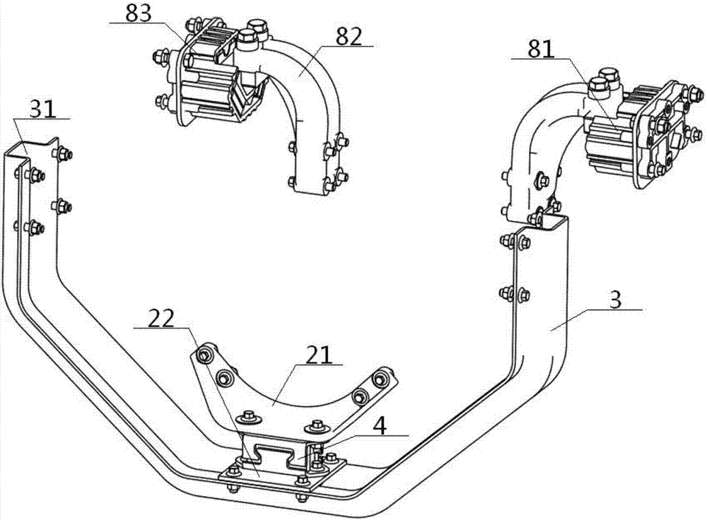
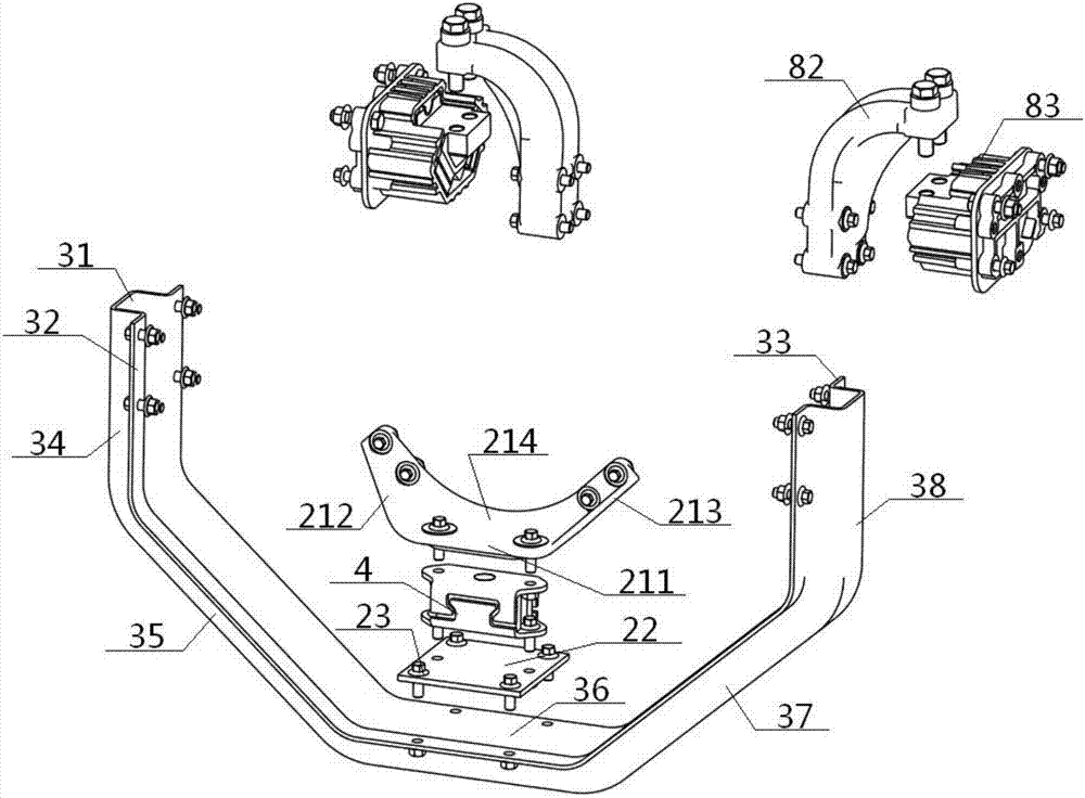
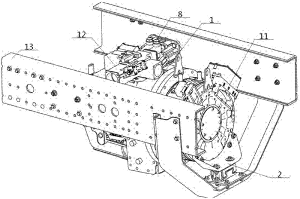
[0065] see Figure 1 to Figure 10, a powertrain suspension system for a pure electric commercial vehicle, comprising a front suspension assembly 2 and a rear suspension assembly 8, the front suspension assembly 2 connects the front end of the powertrain 1 to the frame longitudinal beam 13 The rear suspension assembly 8 connects the rear end of the power assembly 1 with the frame rail 13; the front suspension assembly 2 includes a front suspension bracket 21, a front suspension cushion assembly 4 and the front suspension bracket 3, the front end of the power assembly 1 is connected with the middle part of the front suspension bracket 3 after passing through the front suspension bracket 21 and the front suspension cushion assembly 4 successively, and the front suspension bracket The left and right ends of the frame 3 are connected with the vehicle frame longitudinal beam 13 (such as the outer covering surface of the vehicle frame longitudinal beam 13), the left and right ends of...

Embodiment 2

[0068] Basic content is the same as embodiment 1, the difference is:

[0069] The front suspension bracket 21 includes a front bracket base plate 211, a front bracket left side plate 212, a front bracket right side plate 213 and a U-shaped front bracket rear plate 214, the middle part of the front bracket base plate 211 and the front bracket located below it The suspension cushion assembly 4 is connected, the rear end of the front bracket bottom plate 211 is vertically connected with the bottom end of the middle part of the front bracket rear plate 214, the left and right ends of the front bracket rear plate 214 are connected with the front end of the power assembly 1, The space formed by the interconnection of the front support rear plate 214 and the front support bottom plate 211 is inlaid with the front support left side plate 212 and the front support right side plate 213.

Embodiment 3

[0071] Basic content is the same as embodiment 1, the difference is:

[0072] The front suspension cushion assembly 4 includes an upper frame 5, a rubber body 6 and a lower frame 7 that are connected sequentially from top to bottom and are vulcanized as one. The upper frame 5 includes an upper top plate 51 and its inner and outer sides. Connected upper inner flange 52 and upper outer flange 53, the lower frame 7 includes a lower bottom plate 71 and a lower inner flange 72 connected to its inner and outer sides, a lower outer flange 73, and an upper inner flange 52 , the lower inner flange 72 is on the same plane, the upper outer flange 53 and the lower outer flange 73 are on the same plane, and the rubber body 6 is located on the plane where the upper inner flange 52, the lower inner flange 72 are located and the upper outer flange Between the planes where the flanging 53 and the lower outer flanging 73 are located; the top surface of the upper top plate 51 is connected with t...


PUM


Abstract

The invention discloses a pure electric commercial vehicle power assembly suspension system. According to the system, the front end of a power assemble comprising a motor is connected with the middle of a U-shaped-structure front suspension bracket through a front suspension support and a front suspension bolster assembly in sequence; the left end and the right end of the front suspension bracket are connected with a vehicle frame longitudinal beam; the rear end of the power assembly is connected with the vehicle frame longitudinal beam through a rear suspension support and a rear suspension bolster assembly in sequence; the front suspension support, the front suspension bolster assembly and the front suspension bracket are connected with one another in a vertical tightened mode, and the rear suspension support and the rear suspension bolster assembly are also connected in a vertical tightened mode; the front suspension bolster assembly comprises an upper framework, a rubber body and a lower framework; and the upper framework is internally provided with upper grooves, and the lower framework is internally provided with lower protrusion blocks connected with the corresponding upper grooves in a clamped mode. According to the design, the suspension system is suitable for power assemblies where motors are additionally arranged of pure electric commercial vehicles, and good in vibration isolation effect, the assembling difficulty can be lowered, three-direction limiting can be achieved, the weight is low, and the cost is low.

Description

technical field [0001] The present invention relates to a vehicle power assembly mounting system, in particular to a pure electric commercial vehicle power assembly mounting system and an assembly method thereof, and is particularly suitable for improving the performance of the power assembly of a pure electric commercial vehicle with an added motor. vibration isolation effect. Background technique [0002] In the automotive powertrain mounting device, the gearbox mounting system of a commercial vehicle is used as an auxiliary support device for the powertrain and is connected with the gearbox to ensure that the deformation and displacement of the gearbox do not exceed the allowable range during the operation of the vehicle. At the same time, it has a good ability to suppress vibration, but the vibration isolation effect of the existing commercial vehicle powertrain mount is weak. For example, the vibration isolation rate of Steyr type is only about 45%, which cannot meet th...

Claims


Application Information

Patent Timeline
Patent Type & Authority Applications(China)
IPC IPC(8): B60K1/00B60K17/06
CPCB60K1/00B60K17/06
Inventor 王斐李海雄石裕辉鞠彤晖
Owner DONGFENG COMML VEHICLE CO LTD
Why Eureka
Try Eureka