Construction method for encoder and decoder

A construction method and decoder technology, applied in the direction of instruments, scientific instruments, measuring devices, etc., can solve problems such as complex construction methods and unstable systems, and achieve the effects of simple construction, high sensitivity, and easy distinction

Active Publication Date: 2017-11-14
SICHUAN UNIV
View PDF6 Cites 2 Cited by
  • Summary
  • Abstract
  • Description
  • Claims
  • Application Information

AI Technical Summary

Problems solved by technology

[0008] Aiming at the above-mentioned problems existing in the prior art, the present invention provides a construction method of an encoder and a decoder, which can effectively solve the problems of complex construction methods and unstable systems in the prior art

Method used


Image

  • Construction method for encoder and decoder
  • Construction method for encoder and decoder
  • Construction method for encoder and decoder

Examples


Embodiment 1

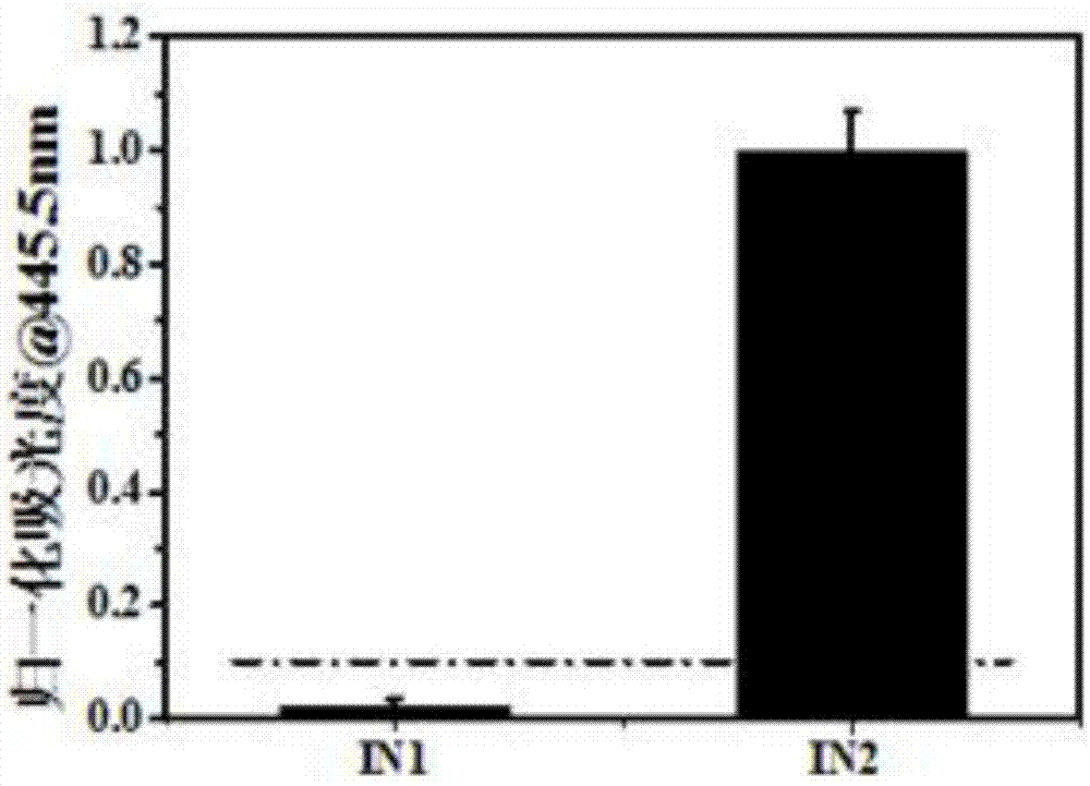
[0042] Example 1 Construction of 2:1 data encoder

[0043] Take 2 EP tubes, numbered 1 and 2, and do the following respectively:

[0044] Take the Tris-HCl buffer solution with pH=7.0-9.0 as the input signal, and add the concentration of 100×10 to tube 1 - 3 mol / L cyanine dye Ⅰ solution and concentration is 10×10 -3 mol / L, pH=8.5 Tris-HCl buffer solution, make the volume of the mixed solution 1mL, and get solution 1. Among them, the concentration of cyanine dye I in solution 1 is 30×10 -6 mol / L.

[0045] Take potassium ion and Tris-HCl buffer solution with pH=7.0-9.0 as input signal, add 1×10 to tube 2 -3 mol / L KCl solution with a concentration of 10×10 -3 mol / L, Tris-HCl buffer solution with pH=8.5 and concentration of 100×10 -3 mol / L cyanine dye I solution, make the volume of the mixed solution 1mL, get solution 2; among them, the concentration of KCl solution in solution 2 is 80×10 -6 mol / L, the concentration of cyanine dye Ⅰ solution is 30×10 -6 mol / L.

[0046] The structural formu...

Embodiment 2

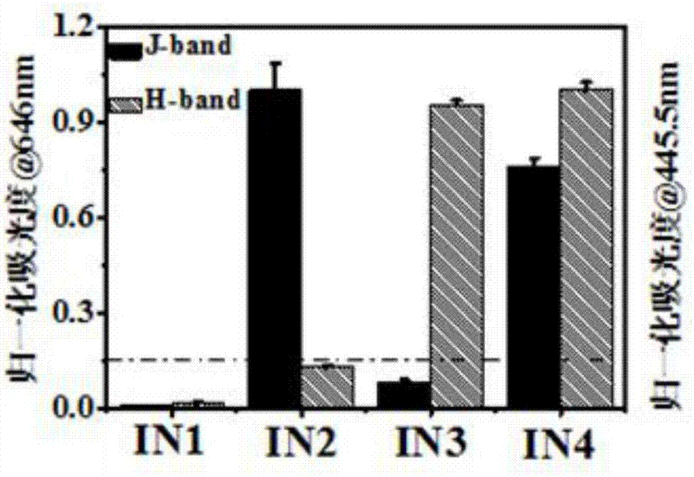
[0051] Example 2 Construction of 4:2 type data encoder

[0052] Take 4 EP tubes, number 1, 2, 3 and 4, and do the following treatments respectively:

[0053] Take the Tris-HCl buffer solution with pH=7.0-9.0 as the input signal, and add the concentration of 100×10 to tube 1 - 3 mol / L cyanine dye Ⅱ solution and the concentration is 10×10 -3 mol / L, pH=8.5 Tris-HCl buffer solution, make the volume of the mixed solution 1mL, to obtain solution 1. Among them, the concentration of the cyanine dye II solution in solution 1 is 30×10 -6 mol / L.

[0054] Take the Tris-HCl buffer solution of pH=3.0-6.0 as the input signal, and add the concentration of 100×10 to tube 2 - 3 mol / L cyanine dye Ⅱ solution and the concentration is 10×10 -3 mol / L, pH=4.0 Tris-HCl buffer solution, make the volume of the mixed solution 1mL, and obtain solution 1. Among them, the concentration of the cyanine dye II solution in solution 1 is 30×10 -6 mol / L.

[0055] Take potassium ion and pH=7.0-9.0 Tris-HCl buffer solution ...

Embodiment 3

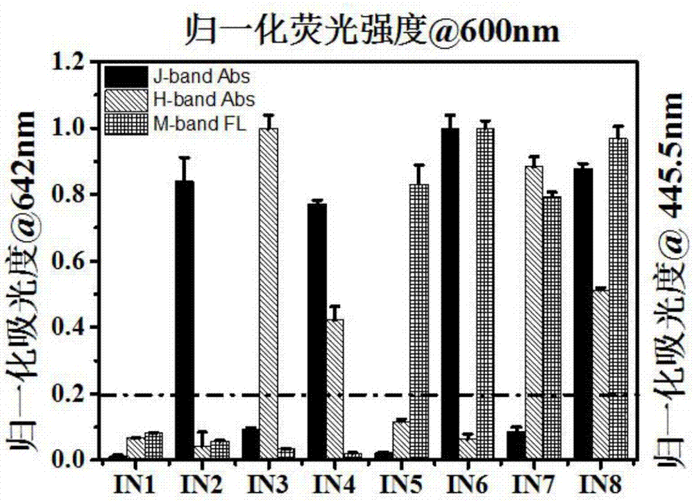
[0065] Example 3 Construction of 8:3 type data encoder

[0066] Take 8 EP tubes, number 1, 2, 3, 4, 5, 6, 7 and 8, and do the following treatments respectively:

[0067] Take the Tris-HCl buffer solution with pH=7.0-9.0 as the input signal, and add the concentration of 100×10 to tube 1 - 3 mol / L cyanine dye Ⅲ solution and the concentration is 10×10 -3 mol / L, pH=8.5 Tris-HCl buffer solution, make the volume of the mixed solution 1mL, and get solution 1. Among them, the concentration of the cyanine dye III solution in solution 1 is 30×10 -6 mol / L.

[0068] Take the Tris-HCl buffer solution of pH=3.0-6.0 as the input signal, and add the concentration of 100×10 to tube 2 - 3 mol / L cyanine dye Ⅲ solution and the concentration is 10×10 -3 mol / L, pH=4.0 Tris-HCl buffer solution, make the volume of the mixed solution 1mL, to obtain solution 2. Among them, the concentration of the cyanine dye III solution in solution 2 is 30×10 -6 mol / L.

[0069] Take potassium ion and Tris-HCl buffer solution ...


PUM


Abstract

The invention provides a construction method for an encoder and a decoder. The method comprises the step of constructing the encoder or the decoder in the manner of taking a cyanine dye solution or cyanine dye solution and double-chain DNA as a template, taking H+, potassium ions, sodium ions and single-chain DNA as input factors, taking a Tris-HCl buffering solution in concentration of (1-100)*10<-3> mol/L and pH of 7.0-9.0 as an one-path input signal, taking the input factors or the combination thereof as parallel input signals and taking diploid or a cyanine dye aggregation state induced by the input factors as an output signal. The encoder and the decoder are high in sensitivity, are at high switch ratio and are easily distinguished; the threshold value is below 0.3; the output signal is easily detached; the dependency on the detecting instrument is less; an absorbing/fluorescence detector can be used for realizing detection; the ionic concentration in the solution can be efficiently, sensitively, simply and quickly detected.

Description

Technical field [0001] The invention belongs to the technical field of encoders and decoders, and specifically relates to a method for constructing an encoder and a decoder. Background technique [0002] Advances in integration technology have continuously upgraded traditional computers to high speed, small size and large storage. However, due to the complexity of integrated circuits, the storage limit of inorganic silicon chips, and the limitations of the traditional computer's own calculation methods, traditional computers have great difficulties in achieving ultra-microstructures, ultra-large storage, and increasing computing speed by orders of magnitude. The DNA chip brought about by the development of biotechnology is much better than the traditional computer in the above aspects. This new type of computer based on the DNA biochemical reaction calculation model is called the DNA computer. [0003] In the DNA computer, the same problem of the traditional computer is that the p...

Claims


Application Information

Patent Timeline
Patent Type & Authority Applications(China)
IPC IPC(8): G01N21/33G01N21/64
CPCG01N21/33G01N21/6486
Inventor 杨千帆杨舒杨春容陈见驰苗家榕黄丹杜媛媛
Owner SICHUAN UNIV
Why Eureka
Try Eureka