A control method for fluorescent transparent ceramic high-power LED light source

A technology of LED light source and transparent ceramics, applied in the field of LED light source, can solve the problems of shortening the service life of light source, damage of light source, uneven heating of ceramics, etc., achieve good market application prospects and improve the effect of cracking

Active Publication Date: 2019-02-05
XIAMEN UNIV
View PDF5 Cites 0 Cited by
  • Summary
  • Abstract
  • Description
  • Claims
  • Application Information

AI Technical Summary

Problems solved by technology

However, there are still cases where the temperature is too high under long-term high-current working conditions
When the temperature reaches a certain value, due to the large temperature difference in different areas of the fluorescent ceramics, the ceramics will be heated unevenly and cracks will occur, causing varying degrees of permanent damage to the light source, thereby shortening the service life of the light source. At the same time, The light effect will also be greatly affected by the

Method used


Image

  • A control method for fluorescent transparent ceramic high-power LED light source
  • A control method for fluorescent transparent ceramic high-power LED light source
  • A control method for fluorescent transparent ceramic high-power LED light source

Examples


Embodiment Construction

[0022] Below in conjunction with accompanying drawing, the present invention will be further described.

[0023] Structural composition and application example description of the embodiment of the present invention:

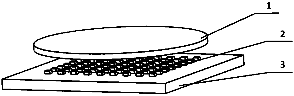
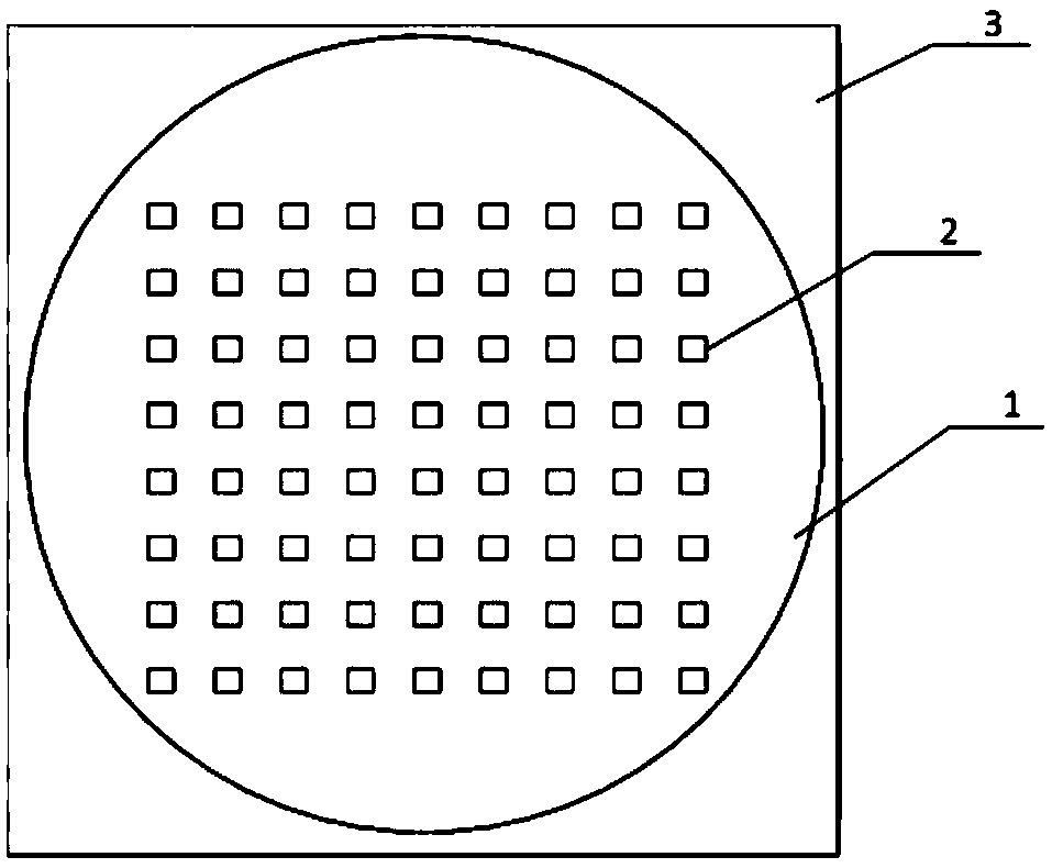
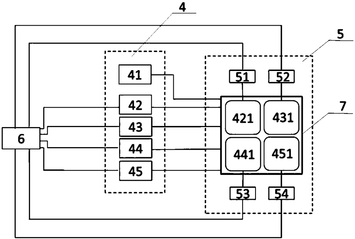
[0024] The component structure of the light source is as follows figure 1 and 2 As shown, mark 1 represents high-quality fluorescent transparent ceramics; mark 2 represents LED chip; mark 3 represents aluminum substrate. In the embodiment, the LED array is divided into four areas, and a red LED chip ( Figure 4 The hollow core chip is represented as a red light LED chip), and the partition method and the number of red light chips can be adjusted according to specific conditions. image 3 It is a block diagram of the structure of the embodiment of the present invention. In this embodiment, a current source module 4 and a light source module 5 are provided. Current source module 4 comprises: mark 41, is used for providing stable current for the red light LED c...


PUM


Abstract

A control method for fluorescent transparent ceramic high-power LED light source, which divides the blue LED chip array of the high-power light source into several regions; adds an equal amount of red LED chips to the blue chips in each partition; and the red light chip are each controlled by a separate current source, keeping the current of the red light chip constant, and monitoring the change value ΔVf of the forward voltage drop of the red light chip within a selected time period through the A / D module in real time, according to ΔT= ΔVf / k is the temperature change ΔT of the red light chip. If ΔT exceeds the limited threshold T1, the output mode of the current source of the blue light chip in the partition is adjusted through the MCU microcontroller, and the line current is changed from a DC current mode to a preset pulse. In the current mode, when the voltage drop of the red chip is less than ΔVf, that is, when the temperature change of the red chip drops to the set threshold T2, the input current mode of the blue chip array is restored to the DC mode.

Description

technical field [0001] The invention relates to LED light sources, in particular to a control method for fluorescent transparent ceramic high-power LED light sources. Background technique [0002] As the fourth-generation lighting source, LED has largely replaced traditional light sources in indoor and outdoor low-power application scenarios due to its high efficiency, energy saving, environmental protection, fast response, and adjustable spectrum. However, the replacement rate of ultra-high power and high power density LED lamps, such as high pole lamps and stadium lamps, is still relatively low. The main reason restricting its widespread use is due to the two factors of heat dissipation and heat resistance of the fluorescent material at the front of the LED light source. Taking a 100W LED light source as an example, the Stokes loss that occurs during the fluorescent down-conversion process will generate nearly 10W of heat. With such a small light source area, so much hea...

Claims


Application Information

Patent Timeline
Patent Type & Authority Patents(China)
IPC IPC(8): H05B33/08H05B44/00
CPCH05B45/00Y02B20/30
Inventor 林岳涂艺吴挺竹郭伟杰吕毅军高玉琳朱丽虹陈忠
Owner XIAMEN UNIV
Why Eureka
Try Eureka