Catheter and guide wire control device for interventional operation and control method of catheter and guide wire control device
A technology for interventional surgery and control devices, applied in the direction of catheters, guide wires, and other medical devices, it can solve the problems of low clamping efficiency and success rate of guide wires and catheters, and achieve uniform and reliable clamping force Large, reliable clamping effect
- Summary
- Abstract
- Description
- Claims
- Application Information
AI Technical Summary
Problems solved by technology
Method used
Image
Examples
Embodiment 1
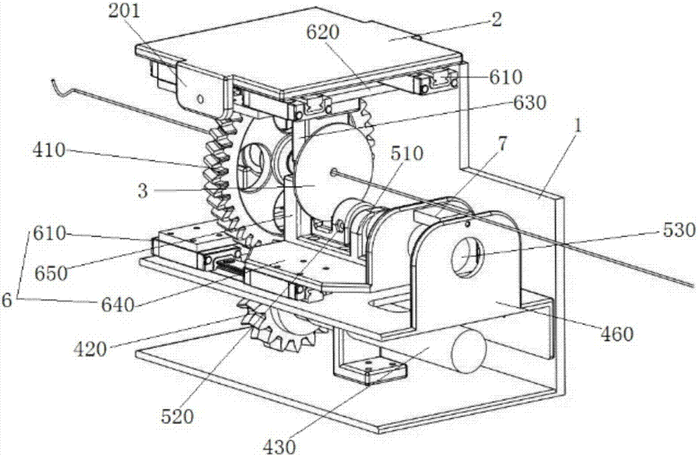
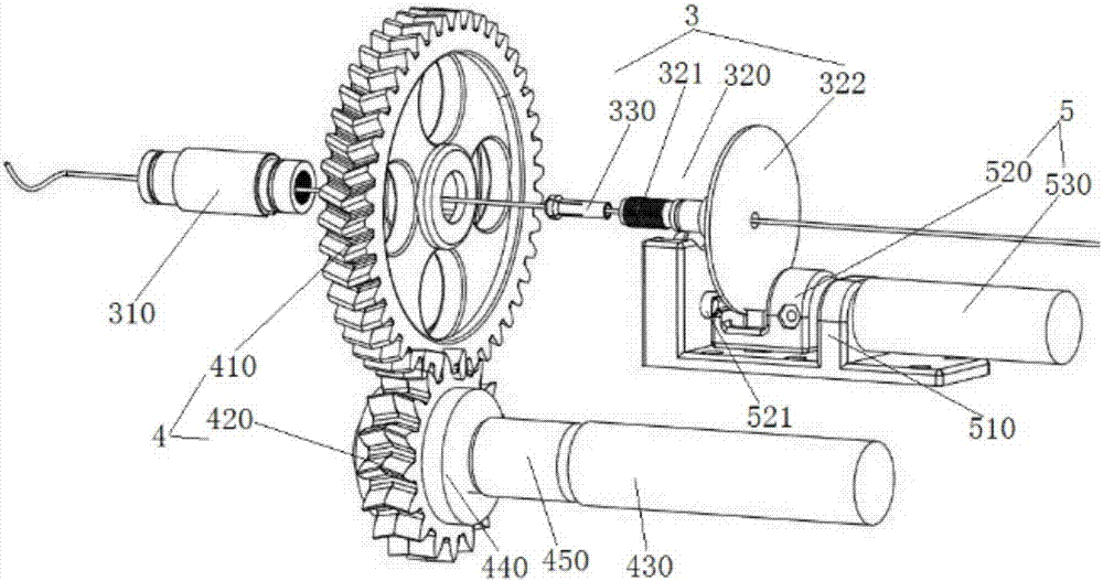
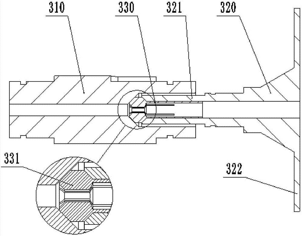
[0059] like figure 1 , figure 2 , image 3 As shown, a catheter guide wire control device for interventional surgery in this embodiment includes a housing 1, a clamping mechanism 3, a sleeve driving assembly 4 and a brake assembly 5, the clamping mechanism 3, and the sleeve driving assembly 4 And brake assembly 5 are all arranged in the housing 1.
[0060] Among them, such as figure 1 As shown, the housing 1 is a U-shaped structure with front and rear side walls. figure 1 In order to clearly see the internal structure of the device, the front wall of the housing 1 has been removed; the top opening of the housing 1 can be detachably installed with the upper cover 2, specifically, an ear is installed on each of the two opposite sides of the upper cover 2. The plate 201, the ear plate 201 and the housing 1 are connected by screws. After the housing 1 is covered with the upper cover 2, a relatively closed space is formed to protect its internal components, which is beneficia...
Embodiment 2
[0069] Using the catheter guide wire control device for interventional surgery in the first embodiment, the catheter or guide wire can be clamped, pushed and pulled, and twisted. Here, the catheter is used as an example to illustrate, and the details are as follows.
[0070] ①Conduit clamping operation
[0071] Firstly, the conduit passes through the brake part 320, the clamp part 330 and the sleeve 310 of the clamping mechanism 3; then, the brake assembly 5 works to brake the brake part 320, specifically, the push-pull electromagnet 530 Get electricity, pull the brake block 520 close to the brake disc 322 of the brake member 320, and contact and press the brake disc 322, the brake member 320 brakes; then, the sleeve drive assembly 4 drives the sleeve 310 of the clamping mechanism 3 to rotate, Specifically, the motor 430 is energized to drive the small herringbone gear 420 to rotate, the small herringbone gear 420 and the large herringbone gear 410 are meshed for transmission,...
Embodiment 3
[0078] A catheter guide wire control device for interventional surgery in this embodiment, on the basis of Embodiment 1, a dynamometer 7 is set between the support plate 460 and the lower support plate 640 on which the brake assembly 5 is installed, for detecting The pushing force of the catheter guidewire. Using this device can not only realize the clamping, pushing and pulling, and twisting operations on the catheter or guide wire in Embodiment 2, but also detect the pushing resistance of the catheter or guide wire. Here, the guide wire is used as an example to illustrate, and the details are as follows.
[0079] The clamping operation of the guide wire is the same as that in Embodiment 2. After the guide wire is clamped, the brake assembly 5 releases the brake part 320 of the clamping mechanism 3, and the clamping mechanism 3 moves along with the guide wire together under the push action of external force. Axial movement, the guide rail slider assembly 6 follows the sliding...
PUM
 Abstract
Description
Claims
Application Information
 - R&D
- Intellectual Property
- Life Sciences
- Materials
- Tech Scout
- Unparalleled Data Quality
- Higher Quality Content
- 60% Fewer Hallucinations
Browse by: Latest US Patents, China's latest patents, Technical Efficacy Thesaurus, Application Domain, Technology Topic, Popular Technical Reports.
© 2025 PatSnap. All rights reserved.Legal|Privacy policy|Modern Slavery Act Transparency Statement|Sitemap|About US| Contact US: help@patsnap.com


