
Mechanically-pumping compressed gas foam fire-extinguishing device

A compressed gas and foam fire extinguishing technology, applied in fire rescue and other fields, can solve the problems of complex control system, high energy consumption, inaccurate mixing ratio measurement, etc., and achieve the effect of accurate mixing ratio, strong adaptability and easy operation

Pending Publication Date: 2017-11-17
CHINA PETROLEUM & CHEM CORP +1
View PDF6 Cites 4 Cited by
  • Summary
  • Abstract
  • Description
  • Claims
  • Application Information

AI Technical Summary

Problems solved by technology

[0004] The technical problem to be solved by the present invention is the problem of inaccurate measurement of mixing ratio, complicated control system and high energy consumption in the prior art. It provides a new mechanically pumped compressed gas foam fire extinguishing device

Method used


Image

  • Mechanically-pumping compressed gas foam fire-extinguishing device
  • Mechanically-pumping compressed gas foam fire-extinguishing device
  • Mechanically-pumping compressed gas foam fire-extinguishing device

Examples


Embodiment 1

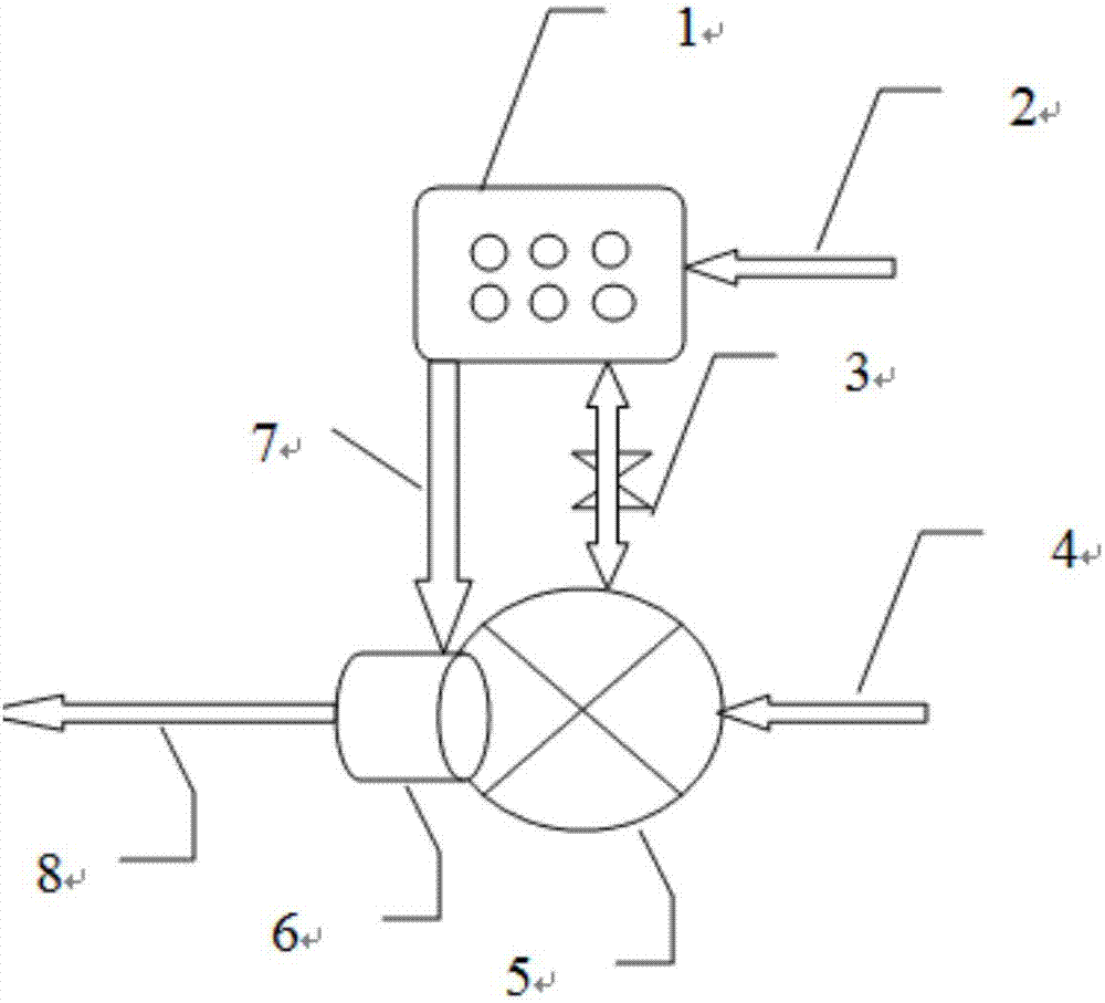
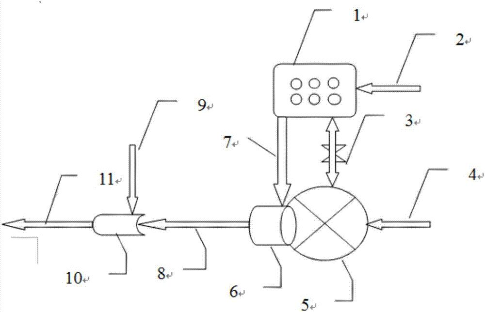
[0016] Such as figure 1 As shown, a mechanically pumped compressed gas foam fire extinguishing device includes a mechanically pumped foam proportional mixing device, a foam generator and a foam delivery pipeline, mainly including 1 foam liquid pump, 2 foam raw liquid inlet, 3 connecting shafts, 4 fire pressure water source, 5 water turbine, 6 mixing chamber, 7 foam stock liquid outlet, 8 foam mixed liquid inlet, 9 air source, 10 foam generator, 11 foam delivery pipeline. The foam liquid pump is connected to the foam liquid inlet, which is used to continuously provide the foam liquid pump with foam liquid; the water turbine is connected to the foam liquid pump and the fire pressure water source, and is used to provide pressure water for the water turbine to generate kinetic energy to drive the foam liquid pump to run; at the outlet of the water turbine The foam mixture generated by the mixing chamber is connected to the foam generator for the foam mixture supplied to the foam g...

Embodiment 2

[0023] 1 Foam liquid pump, 2 Foam raw liquid inlet, 3 Connecting shaft, 4 Fire-fighting pressure water source, 5 Water turbine, 6 Mixing chamber, 7 Foam raw liquid outlet, 8 Foam mixed liquid inlet, 9 Air source, 10 Foam generator, 11 Foam delivery pipe road.

[0024] Fill the raw liquid storage tank with 3% foam fire extinguishing agent, the inlet and outlet pipe diameters of the foam proportional mixing device and the foam generator are both DN200, and the compressed gas is composed of a group of 40L compressed air cylinders with a pressure of 10Mpa, which are collected after decompression in the header.

[0025] The 3% foam fire extinguishing agent enters the foam liquid pump 1 from the liquid inlet 2, starts the water pump, and the water from the fire pressure water source 4 enters the water turbine 5, and the water turbine 5 drives the foam liquid pump 1 to rotate, and opens the water-foam liquid selection valve to make the foam The raw liquid enters the mixing chamber 6...


PUM


Abstract

The invention relates to a mechanically-pumping compressed gas foam fire-extinguishing device, and mainly solves the problems of inaccurate mixing ratio measurement, complex control system and high energy consumption in the prior art. The problem is solved well through adopting the technical scheme that the mechanically-pumping compressed gas foam fire-extinguishing device is adopted, and comprises a foam concentrate pump 1, a foam concentrate inlet 2, a connection shaft 3, a fire-fighting pressure water source 4, a water turbine 5, a mixing cavity 6, a foam connection outlet 7, a foam mixed solution inlet 8, a gas source 9, a foam generator 10 and a foam conveying pipeline 11. The mechanically-pumping compressed gas foam fire-extinguishing device can be used in fire-fighting fire extinguishment.

Description

technical field [0001] The invention relates to a mechanically pumped compressed gas foam fire extinguishing device. Background technique [0002] When extinguishing gas, liquid and solid fires, foam fire extinguishing systems are commonly used, mainly including fixed, semi-fixed and mobile foam fire extinguishing systems. Among them, the foam proportional mixing device is the central axis area of ​​the fire extinguishing system. Whether the ratio is accurate and the operation is smooth is related to the effect of on-site fire fighting. There are two kinds of proportional mixing devices commonly used at present. One is a pressure foam proportional mixing device. The disadvantage is that it cannot continuously provide foam stock solution, the capsule is prone to aging and damage, and the pressure storage tank is small and the production cost is high. The other is a balanced pressure foam proportional mixing device, which occupies a large area, and the balance valve has certa...

Claims


Application Information

Patent Timeline
IPC IPC(8): A62C5/02A62C31/12
CPCA62C5/02A62C31/12
Inventor 谈龙妹蒋婷婷吴京峰尚祖政王俊杨郎需庆牟小冬林涛
Owner CHINA PETROLEUM & CHEM CORP
Learn More