Driving impeller assembly in sander

A grinding machine and impeller technology, applied in the direction of manufacturing tools, grain processing, wood processing equipment, etc., can solve the problems of affecting the use effect, belt wheel offset slipping, poor positioning effect, etc., to achieve good fastening effect, reliable connection, The effect of reducing errors

Pending Publication Date: 2017-11-17
NANJING ZMAKE MACHINERY CO LTD
View PDF8 Cites 0 Cited by
  • Summary
  • Abstract
  • Description
  • Claims
  • Application Information

AI Technical Summary

Problems solved by technology

In the existing grinding machine, the main shaft and the pulley are connected by a key, and the axial limit of the pulley on the main shaft is realized by the pin shaft. This kind of direction positioning effect is poor, and after a long time of use, the pulley is prone to d

Method used


Image

  • Driving impeller assembly in sander
  • Driving impeller assembly in sander
  • Driving impeller assembly in sander

Examples


Embodiment Construction

[0021] The present invention will be further described below in conjunction with the accompanying drawings.

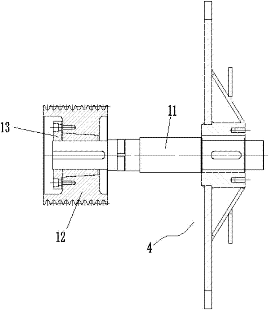
[0022] Such as Figure 1 to Figure 6 , the invention discloses a drive impeller assembly in a grinding machine, including a main shaft 11, a pulley 12, an expansion sleeve 13 and an impeller 4, the pulley 12 is connected to the main shaft 11 through an expansion sleeve 13, and the connection between the pulley 12 and the expansion sleeve 13 They are fixedly connected by screws, and the main shaft 11 and the expansion sleeve 13 are keyed. The impeller 4 is sheathed on the main shaft 11 , and the impeller 4 is connected to the main shaft 11 by a key.

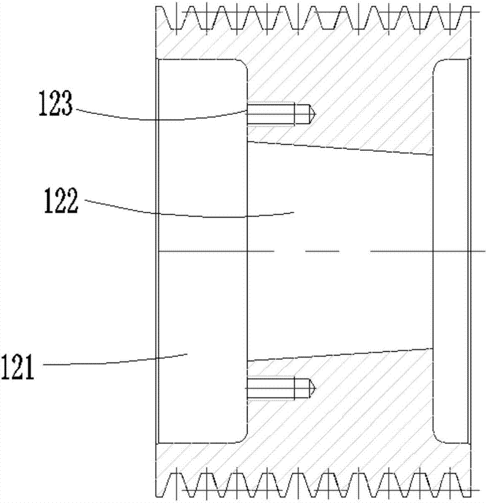
[0023] A fixing hole 121 and a tapered hole 122 are provided in the axial direction of the pulley 12 , the fixing hole 121 and the tapered hole 122 are connected, and a threaded hole 123 is provided in the fixing hole 121 .

[0024] The outer peripheral wall of the expansion sleeve 13 is a tapered surface structure, and ...


PUM


Abstract

The invention discloses a driving impeller assembly in a sander. The driving impeller assembly comprises a main shaft, a belt wheel, an expanding sleeve and an impeller. The belt wheel is connected to the main shaft through the expanding sleeve, the belt wheel is fixedly connected with the expanding sleeve through screws, the main shaft is in key connection with the expanding sleeve, and the impeller is arranged on the main shaft in a sleeving mode, and is in key connection with the main shaft. The driving impeller assembly in the sander is good in fastening effect and reliable in connection, and the belt wheel does not slip; locating grooves can effectively locate a blade mounting plate, thus mounting is facilitated and errors are reduced.

Description

Technical field: [0001] The invention relates to a driving impeller assembly in a grinder. Background technique: [0002] The sieve ring grinder grinds the shavings into fine shavings, which are used as the surface material of the particleboard. It is composed of machine base, grinding screen ring, impeller, vibrating feeder, magnetic separation, heavy object separator and other parts, and grinds large shavings into fine shavings that meet certain process requirements. In the existing grinding machine, the main shaft and the pulley are connected by a key, and the axial limit of the pulley on the main shaft is realized by the pin shaft. This kind of direction positioning effect is poor, and after a long time of use, the pulley is prone to damage. Offset slippage affects the use effect, and when the impeller in the grinder is fixing the blade, the blade mounting plate is not positioned on the impeller, so after the blade is installed, there is a large error, which affects the...

Claims


Application Information

Patent Timeline
IPC IPC(8): B02C18/18B27L11/02
CPCB02C18/18B27L11/02
Inventor 王涛
Owner NANJING ZMAKE MACHINERY CO LTD
Why Eureka
Try Eureka