Semiconductor material heat treatment device for mobile terminal

A heat treatment device and mobile terminal technology, which is applied in semiconductor/solid-state device manufacturing, lighting and heating equipment, furnaces, etc., can solve problems such as inconvenience, danger, and air replacement leakage in the unloading process, and achieve convenient control and adjustment, and convenient sintering Process, increase the effect of heating purpose

Pending Publication Date: 2022-03-11
临沂安信电气有限公司
View PDF8 Cites 0 Cited by
  • Summary
  • Abstract
  • Description
  • Claims
  • Application Information

AI Technical Summary

Problems solved by technology

[0006] In order to solve the above-mentioned technical problems, the present invention provides a semiconductor material heat treatment device for mobile terminals to solve the problem of poor sealing performance of existing equipment for sintering crystalline silicon, which is prone to leakage due to air replacement during processing. The performance is not stable enough, which makes the sealing operation too cumbersome, and the temperature of crystalline silicon after sintering is high, and the unloading process is inconvenient and dangerous

Method used


Image

  • Semiconductor material heat treatment device for mobile terminal
  • Semiconductor material heat treatment device for mobile terminal
  • Semiconductor material heat treatment device for mobile terminal

Examples


Embodiment

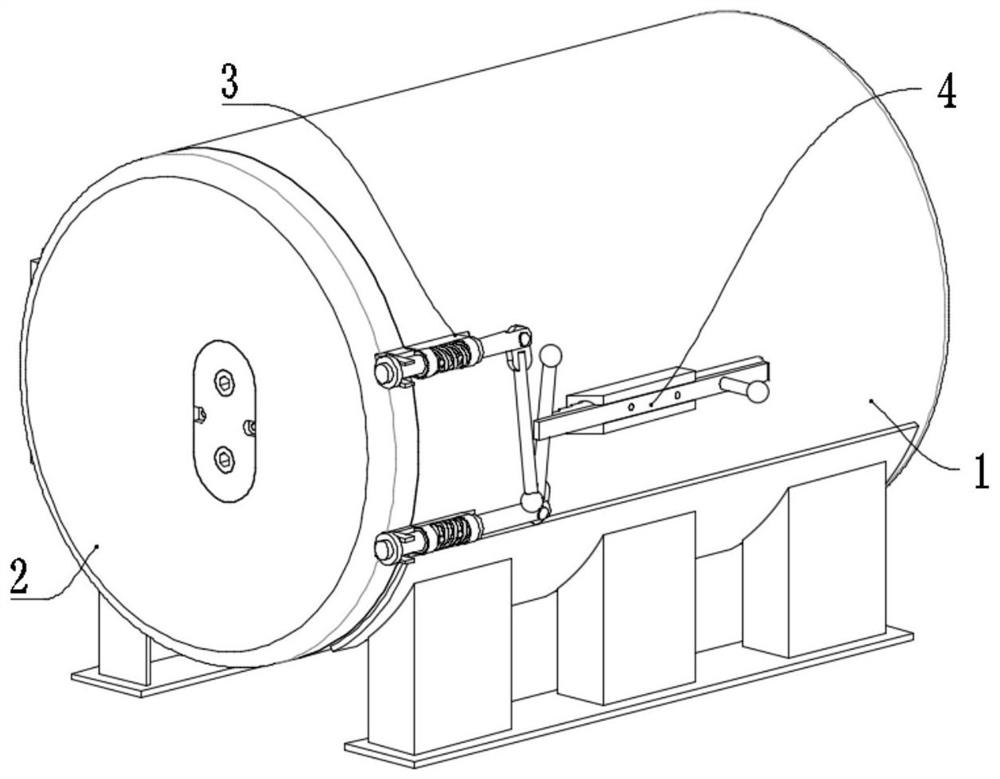
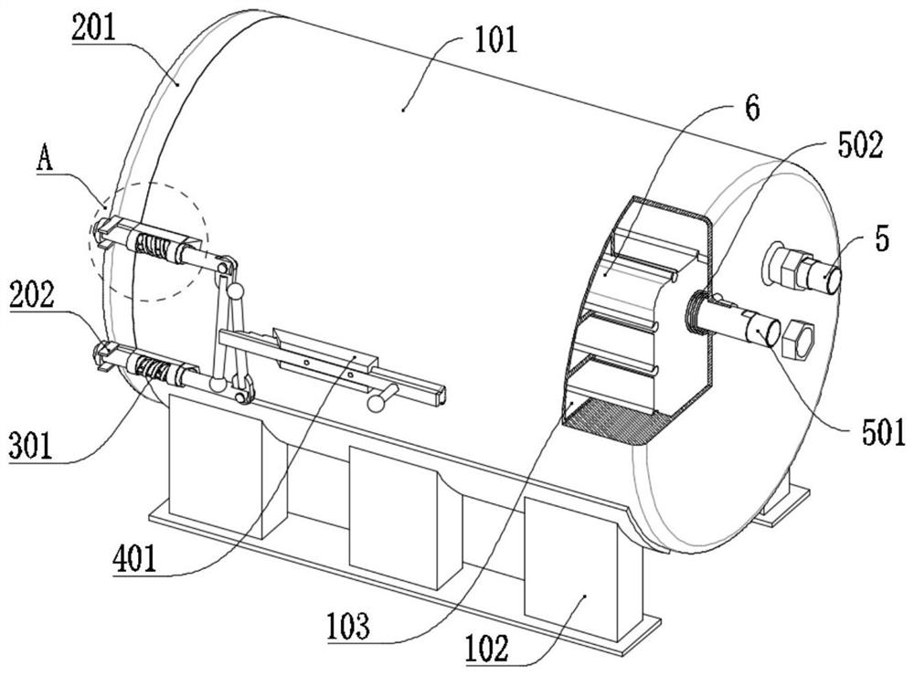
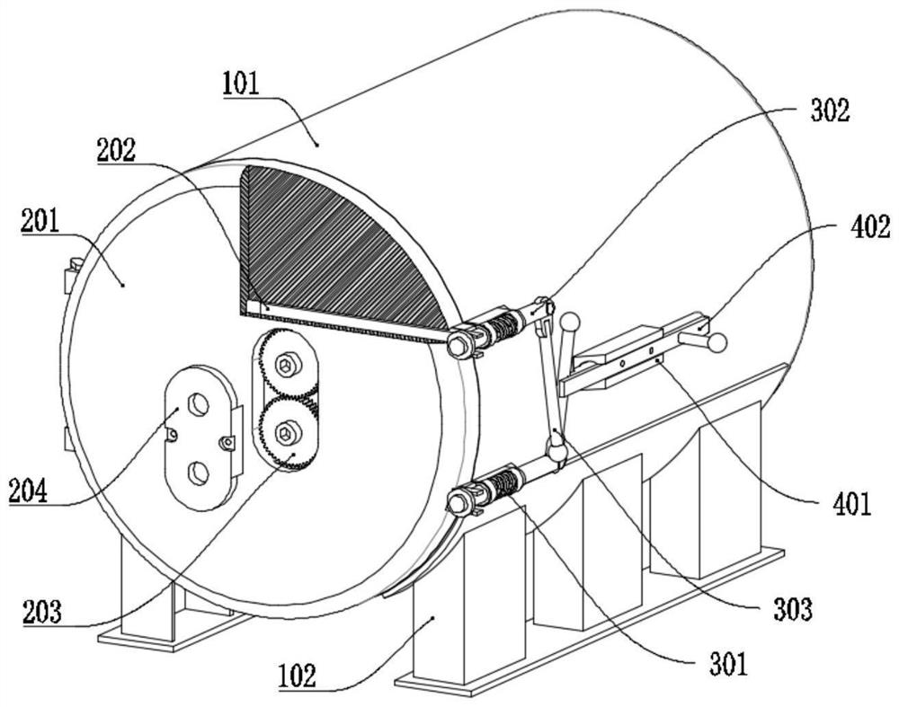
[0061] as attached figure 1 to attach Figure 9 Shown:

[0062] The present invention provides a semiconductor material heat treatment device for mobile terminals, including a tank device 1;

[0063] The sealing structure 2, the sealing structure 2 is a vertical plate structure, the sealing structure 2 is hingedly installed at the front end of the tank device 1, the tank device 1 includes: the installation tank 101, the installation tank 101 is a barrel-shaped structure, and the inner wall is fixed with a spacer Plates 103 and spacer plates 103 are arranged in a circular array, and the spacer plates 103 form the grooves with a square structure on the inner wall. Through the square grooves formed by the spacer plates 103, the effect that the inner box structure 6 is convenient to install is realized. Each group of spacers The ends of the plates 103 are all equipped with heating structures. By setting the ends of the spacer plates 103 as heating structures, the heating purpose...

no. 2 example

[0088] Lifting device 8, the lifting device 8 is a sliding structure, and the lifting device 8 carries the bearing device 7.

[0089] Wherein, lifting device 8 includes:

[0090] Mounting plate 801, the mounting plate 801 is a rectangular plate structure, wheels are installed on the mounting plate 801, through the grooves with wheels, the lifting device 8 is easy to move, the middle of the mounting plate 801 is provided with a mounting groove;

[0091] The support frame 802, the support frame 802 is a C-shaped frame structure, the support frame 802 is provided with two types of six groups in total, the first three groups of support frames 802 are hingedly installed on the mounting plate 801;

[0092] The carrier 803, the carrier 803 is a frame structure, the ends of the first type of support 802 are connected to the carrier 803, and the bottom of the carrier 803 is hingedly installed with the second type of support 802;

[0093] Bottom slide 806, bottom slide 806 is a long pl...


PUM


Abstract

The invention provides a semiconductor material sintering treatment device for a mobile terminal. The semiconductor material sintering treatment device comprises a tank body device, the sealing structure is of a vertical disc structure and is hinged to the front end of the tank body device, fixing assemblies are arranged at the contact position of the sealing structure and the tank body device, the fixing assemblies are divided into an upper group and a lower group, an auxiliary structure is fixed to the outer wall of the tank body device, and the auxiliary structure is transversely fixed. An external connection structure is arranged at the rear end of the tank body device; the inner box structure is of a rectangular structure, the inner box structure is installed in the tank body device in an embedded mode, and a bearing device is installed at the inner lower end of the inner box structure in a sliding mode; the lifting device is of a sliding structure, the bearing device is mounted on the lifting device in a bearing mode, the bearing device sliding to the bearing frame can be fixed by rotating the fixing rod, and the lifting device is safer and more stable in the conveying process of the bearing device.

Description

technical field [0001] The invention belongs to the technical field of sintering treatment equipment, and more specifically relates to a semiconductor material heat treatment device for mobile terminals. Background technique [0002] With the progress and development of society, electronic information technology is gradually improving, and the use of electronic equipment is also gradually increasing. Smart devices such as mobile phones and computers cannot leave the chip, and the chip is made by using a photolithography machine to use ultraviolet light on the semiconductor silicon wafer. Engraving, chemical and silver plating are performed on the semiconductor silicon wafer that has been engraved to realize the formation of micro-semiconductor circuits on the semiconductor silicon wafer. The semiconductor used is made of crystalline silicon, which usually needs to be sintered during production. . [0003] Application number: In the patent of CN201810108129.2, the invention ...

Claims


Application Information

Patent Timeline
Patent Type & Authority Applications(China)
IPC IPC(8): F27B5/00F27B5/12F27B5/13F27B5/06H01L21/67
CPCF27B5/00F27B5/12F27B5/13F27B5/06H01L21/67098
Inventor 诸葛欣欣
Owner 临沂安信电气有限公司
Why Eureka
Try Eureka