
Rotary shaft drilling machining fixing seat in workshop

A fixed seat and shaft technology, used in large fixed members, metal processing equipment, metal processing machinery parts, etc., can solve the problems of difficult to control the size of the force, uneven clamping force, time-consuming and laborious, and achieve easy and fast clamping. The effect of holding and fixing, improving product quality, and simple and convenient operation

Inactive Publication Date: 2017-11-17
ANHUI YUETIAN SPECIAL AXLE
View PDF5 Cites 0 Cited by
  • Summary
  • Abstract
  • Description
  • Claims
  • Application Information

AI Technical Summary

Problems solved by technology

[0002] The clamping seat is a mechanical device used to clamp the workpiece on the machine tool. When using it on a milling machine, it is necessary to fix the chuck on the milling machine table first, and then manually operate the chuck to clamp the cylindrical workpiece; this operation is laborious , and for large-scale cylindrical workpieces, it is more difficult to clamp. There is also a clamping mold in the prior art, which is also clamped by pneumatically pushing the clamping block, but the clamping blocks are all cuboids, which is labor-intensive and expensive. It is not easy to control the magnitude of the applied force, and the clamping force will also appear uneven, resulting in unqualified product quality. As a clamping and positioning tool for the workpiece, the clamping device is widely used in the processing and manufacturing of the workpiece
The pressure plate of the existing clamping device uses an ordinary cylinder as the power source, and the piston rod of the cylinder drives the jaws or the pressure plate to clamp the workpiece. However, when the workpiece is taken out and the workpiece is placed in the processing position, the The obstruction of the jaws or the pressure plate makes it inconvenient to take out or put in the workpiece
[0003] In the prior art, when processing some large parts, especially some shaft mechanical parts, it is difficult to clamp the workpiece, it is not easy to fix, and the workpiece is easy to loose, which affects the processing quality and accuracy

Method used


Image

  • Rotary shaft drilling machining fixing seat in workshop

Examples


Embodiment Construction

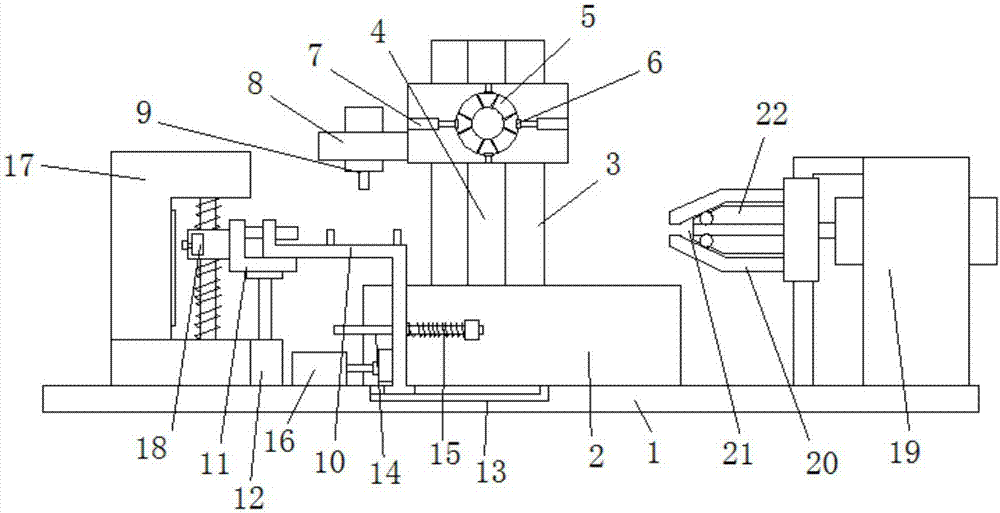
[0010] Referring to the accompanying drawings, a fixing seat for drilling and processing of rotating shafts in a workshop includes a base 1 on which a cleaning pool 2 is fixedly installed. The side wall of 3 is provided with a chute 4, and a cylindrical jacket 5 is slidably installed in the chute 4, and a plurality of annularly distributed clamping blocks 6 are arranged on the side wall of the jacket 5. Each clamping block 6 is regulated by adjusting rod 7 to carry out clamping operation respectively, and the center of described jacket 5 is provided with workpiece hole, and the side wall of described cylindrical jacket 5 is provided with support plate 8, and described support A drill bit 9 is fixedly installed on the side wall of the plate 8, a support platform 10 is provided below the drill bit 9, and the left end of the support platform 10 is lapped on the sliding support seat 11, and the bottom of the sliding support seat 11 is provided with Jacking cylinder 12, the jacking...


PUM


Abstract

The invention discloses a rotary shaft drilling machining fixing seat in a workshop. The rotary shaft drilling machining fixing seat comprises a base. The rotary shaft drilling machining fixing seat is characterized in that the base is fixedly provided with a cleaning pool, one side of the cleaning pool is provided with a height adjustment support column, the side wall of the support column is provided with a sliding slot, the sliding slot is internally provided with a cylindrical jacket in a sliding manner, the side wall of the jacket is provided with a plurality of clamping blocks which are distributed annularly, each clamping block is adjusted by an adjustment rod to perform clamping operation, the center of the jacket is provided with a workpiece hole, and the side wall of the cylindrical jacket is provided with a supporting plate. The rotary shaft drilling machining fixing seat is simple in structure, a shaft type workpiece which is difficult to clamp is convenient to fix, drilling can be achieved at the same time, cleaning is rapid, and the rotary shaft drilling machining fixing seat is firm and stable to use.

Description

technical field [0001] The invention relates to the technical field of machine tool fixtures, in particular to a fixing seat for drilling and processing a rotating shaft in a workshop. Background technique [0002] The clamping seat is a mechanical device used to clamp the workpiece on the machine tool. When using it on a milling machine, it is necessary to fix the chuck on the milling machine table first, and then manually operate the chuck to clamp the cylindrical workpiece; this operation is laborious , and for large-scale cylindrical workpieces, it is more difficult to clamp. There is also a clamping mold in the prior art, which is also clamped by pneumatically pushing the clamping block, but the clamping blocks are all cuboids, which is labor-intensive and expensive. It is not easy to control the magnitude of the applied force, and the clamping force will also appear uneven, resulting in unqualified product quality. As a clamping and positioning tool for the workpiece, ...

Claims


Application Information

Patent Timeline
Patent Type & Authority Applications(China)
IPC IPC(8): B23Q1/26B23Q3/02B23Q11/00
CPCB23Q1/26B23Q3/02B23Q11/00
Inventor 李少芳周忠秋郑斌
Owner ANHUI YUETIAN SPECIAL AXLE
Learn More