Upright type vertical conveying device for non-woven fabric drying and setting machine

A conveying device and non-woven fabric technology, applied in textiles and papermaking, equipment for drying fabrics, fabric surface trimming, etc., can solve problems such as abnormal production and tearing of cloth edges under force, and reduce the risk of tearing and clamping Good holding power and simple structure

Pending Publication Date: 2017-11-17
JIANGSU LITTLE SUN TECH DEV CO LTD
View PDF7 Cites 2 Cited by
  • Summary
  • Abstract
  • Description
  • Claims
  • Application Information

AI Technical Summary

Problems solved by technology

[0004] Also, if you use horizontally running cloth clips as the carrier for transporting non-woven fabrics, since the fabric is conveyed horizontally, the weight of the fabric itself will cause excessive force on the two edges of the fabric and cause tearing, because no

Method used


Image

  • Upright type vertical conveying device for non-woven fabric drying and setting machine
  • Upright type vertical conveying device for non-woven fabric drying and setting machine
  • Upright type vertical conveying device for non-woven fabric drying and setting machine

Examples


Embodiment 1

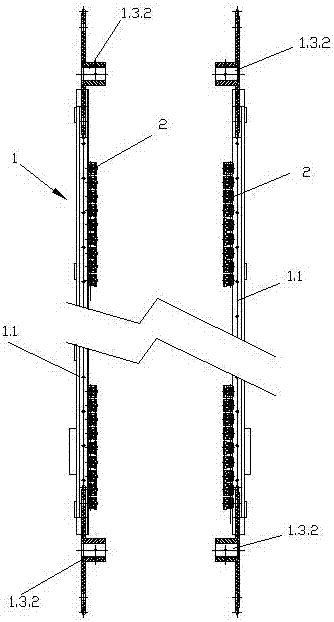
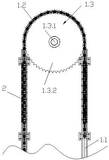
[0026] Embodiment 1: A vertical vertical conveying device for a non-woven fabric drying and setting machine, including two sets of symmetrical vertical conveying units 1 on the left and right, and the thin non-woven fabric is clamped between the two vertical conveying units 1 in a vertical state In between, the vertical conveying unit 1 includes two vertical guide rails 1.1 arranged at intervals in parallel, a closed-loop conveying chain 1.2 arranged in the two vertical guide rails 1.1, and a driving conveyor arranged above and below the two vertical guide rails 1.1. The chain driving device 1.3 driven clockwise by the chain 1.2 and the cloth clip 2 installed on each link 1.2.1 of the conveyor chain 1.2, the cloth clip 2 and the chain link 1.2.1 are vertically installed, and the two sides of the thin non-woven fabric Clamped on cloth clip 2. The chain driving device 1.3 comprises an upper and lower drive shaft 1.3.1, an upper and lower sprocket 1.3.2 installed on the upper and...

Embodiment 2

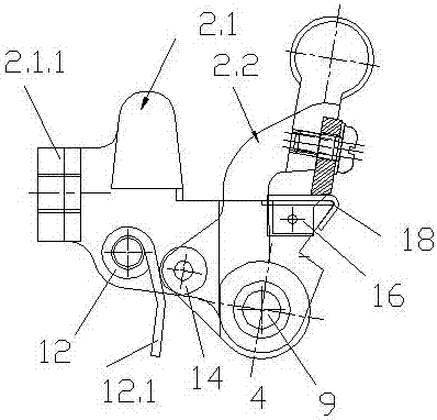
[0027] Embodiment 2: Referring to Embodiment 1, the cloth clip 2 includes a main body base 2.1 and a knife clip 2.2 hinged with the main body base 2.1. The main body base 2.1 includes a tail plate 2.1.1 at the left end and a knife table 2.1.2 at the right end And the front and rear two side plates 2.1.3 that are symmetrical between the tail plate 2.1.1 and the tool rest 2.1.2, the three are surrounded to form a hollow frame structure, and the front and rear two side plates 2.1.3 are provided with a Set of torsion spring holes 3, the right side of the torsion spring hole 3 is provided with a group of spindle holes 4, the knife clip 2.2 includes the hinged arm 2.2.1, the hinged hole 5 opened at the bottom of the left end of the hinged arm 2.2. .1 a group of lugs 6 located at the upper right end of the hinged hole 5, a knife edge platform 7 near the right end of the hinged arm 2.2.1, and a knife holder 8 at the right end of the hinged arm 2.2.1, the hinged hole 5 corresponds to th...


PUM


Abstract

The invention provides an upright type vertical conveying device for a non-woven fabric drying and setting machine. The upright type vertical conveying device comprises left and right groups of symmetrical vertical conveying units, wherein a thin non-woven fabric is clamped between the two vertical conveying units at a vertical state; each vertical conveying unit comprises two upright type guide rails which are arranged in parallel and at interval, a conveying chain which is arranged in the two upright type guide rails and forms a closed loop, chain driving devices which are arranged above and below the two upright type guide rails and are used for driving the conveying chain to rotate along a clockwise direction, and a cloth clip which is arranged on each chain section of the conveying chain; the cloth clips and the chain sections are vertically mounted and two cloth edges of the thin non-woven fabric are clamped on the cloth clips. The upright type vertical conveying device has the effects of stably clamping and effectively preventing cloth edges of ultrathin non-woven fabric edges from being torn.

Description

technical field [0001] The invention relates to the field of drying and setting machines for non-woven fabrics, in particular to a conveying device for ultra-thin non-woven fabrics. Background technique [0002] At present, the equipment for drying and setting non-woven fabrics after dipping in the market uses horizontal chains and needle plates or cloth clips in horizontal or vertical guide rails as carriers for transporting fabrics. In addition to being unable to use the needle plate and cloth clips normally, the drying (or setting machine) also has defects such as large equipment footprint and low thermal efficiency. [0003] The original thin non-woven fabric (9g / m²) is pressed into the needle plate after dipping, because its material is extremely thin, it is easy to be rolled and torn by the brush. The weight of the slurry itself, the larger the width of the door, the greater the tension on the second selvedge; [0004] Also, if you use horizontally running cloth clip...

Claims


Application Information

Patent Timeline
IPC IPC(8): D06C3/02D06C3/04
CPCD06C3/02D06C3/025D06C3/04D06C2700/09
Inventor 张才南张盛周燕钱祖勤
Owner JIANGSU LITTLE SUN TECH DEV CO LTD
Why Eureka
Try Eureka