Connecting structure of beam-column joint of steel pipe concrete combined column

A technology of steel pipe concrete and connection structure, which is applied in the direction of building structure and construction, and can solve problems such as brittle failure at joints, large residual stress of steel, and influence on external wall installation, so as to avoid welding work on the construction site and eliminate three Concentration of axial stress and high degree of assembly

Active Publication Date: 2017-11-17
QINGDAO TECHNOLOGICAL UNIVERSITY
View PDF8 Cites 2 Cited by
  • Summary
  • Abstract
  • Description
  • Claims
  • Application Information

AI Technical Summary

Problems solved by technology

However, the above two joint forms have the following disadvantages: 1. Diaphragm joints, the diaphragm and the flange of the beam are on the same horizontal plane. This joint form makes the column disconnected on each floor, and the welding volume is large. The difficulty is high, and at the same time, the steel will generate a large residual stress, which makes the joints prone to brittle failure; 2. T

Method used


Image

  • Connecting structure of beam-column joint of steel pipe concrete combined column
  • Connecting structure of beam-column joint of steel pipe concrete combined column
  • Connecting structure of beam-column joint of steel pipe concrete combined column

Examples


Embodiment Construction

[0027] The present invention will be further described below in conjunction with accompanying drawing.

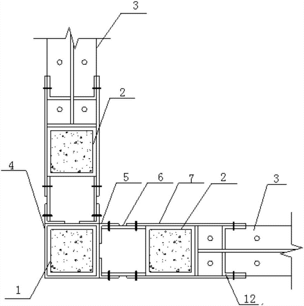
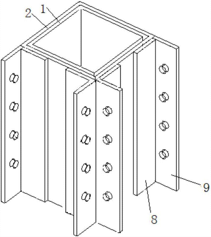
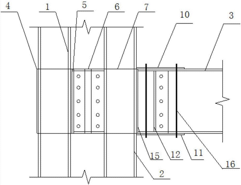
[0028] Such as Figure 1-4 As shown, the connection structure of the steel pipe concrete composite column-beam-column joint of the present invention comprises a central square steel pipe 1, side-end square steel pipes 2 and H-shaped steel beams 3, and the central square steel pipe and the side-end square steel pipes are connected by a column connection assembly .

[0029] The column connection assembly includes sleeve 4, column angle steel connector 5, connecting plate I6 and connecting plate II7. The sleeve is welded on the central square steel pipe. A column angle steel connector, the column angle steel connector includes side I8 and side II9 perpendicular to each other, side I is welded on the sleeve, side II is on the same plane as the side of the sleeve; connecting plate II is symmetrically arranged on the side The two sides of the end square steel pipe are on the sa...


PUM


Abstract

The invention relates to the field of building structure structural parts, and discloses a connecting structure of a beam-column joint of a steel pipe concrete combined column. The connecting structure of the beam-column joint of the steel pipe concrete combined column comprises a center square steel pipe, an edge end square steel pipe and a steel beam. The center square steel pipe is connected with the edge end square steel pipe through a column connecting assembly. The edge end square steel pipe is connected with the steel beam through a beam connecting assembly. According to the connecting structure of the beam-column joint of the steel pipe concrete combined column, the center square steel pipe is connected with the end square steel pipe through the column connecting assembly, the rigidity of the joint is increased greatly, and meanwhile, twisting of the center square steel pipe and the end square steel pipe is prevented and controlled effectively; according to the connecting structure of the beam-column joint of the steel pipe concrete combined column, beams and columns are connected through bolts, direct welding is avoided, the purpose of beam-column separation is achieved, brittle failure which occurs in the beam-column joint is avoided effectively, so that plastic hinge offset is caused, and seismic requirements of strong column-weak beam and strong joint-weak structural part are met; and according to the connecting structure of the beam-column joint of the steel pipe concrete combined column, all structural parts and connecting parts are machined and completed in a machining factory, the beams and the columns on a construction site are connected by using the bolts, welding working on the construction site is avoided effectively, the degree of assembly is high, and installing is convenient and fast.

Description

technical field [0001] The invention relates to the field of building structural components, in particular to a connection structure of a steel pipe concrete composite column-beam-column node. Background technique [0002] The steel pipe concrete composite column is mainly used in multi-storey and small high-rise residential buildings. Its advantages lie in its small cross-sectional size, flexible cross-sectional form, and the equal width of the column and the wall to avoid indoor convex corners caused by excessive column cross-sections and increase the use of the house. The area improves the occupancy experience of the owners. [0003] The steel tube concrete composite column structure is connected by steel beams to form an overall structural form. The connection nodes in the beam-column connection area become one of the key factors in the structure. The connection of steel pipe columns in the node area should meet the requirements of strong columns and weak beams, strong ...

Claims


Application Information

Patent Timeline
IPC IPC(8): E04B1/58
CPCE04B1/185
Inventor 杨晓明刘凯马哲昊
Owner QINGDAO TECHNOLOGICAL UNIVERSITY
Why Eureka
Try Eureka