Anchor rod system used for gas extraction and hydraulic fracturing and extraction method

A technology of gas drainage and hydraulic fracturing, which is applied in the direction of gas discharge, bolt installation, mining fluid, etc. It can solve the problem of rock burst easily occurring in deep coal mines, large amount of drilling in gas drainage roadways, and gas drainage problems. Low system efficiency and intelligence, to achieve the effect of inhibiting the deformation of the surrounding rock of the roadway, preventing rock burst, and preventing local concentration of gas

Pending Publication Date: 2017-11-17
HUNAN UNIV OF SCI & TECH
View PDF10 Cites 7 Cited by
  • Summary
  • Abstract
  • Description
  • Claims
  • Application Information

AI Technical Summary

Problems solved by technology

[0004] In order to solve the above-mentioned safety problems such as the large amount of drilling in the gas drainage roadway, the low efficiency and intelligence of the gas drainage system, and the proneness to rock burst in deep coal mines, the present invention provides a gas drainage and water pressure induced The cracked bolt system and drainage method have high gas drainage efficiency, can monitor and alarm local gas anomalies in real time, have a wide range of applications, have a small amount of drilling and low production costs, and realize the integration of support and gas drainage. Expected Effects of Efficient Gas Drainage

Method used


Image

  • Anchor rod system used for gas extraction and hydraulic fracturing and extraction method
  • Anchor rod system used for gas extraction and hydraulic fracturing and extraction method
  • Anchor rod system used for gas extraction and hydraulic fracturing and extraction method

Examples


Embodiment Construction

[0027] The present invention will be further described below in conjunction with the accompanying drawings.

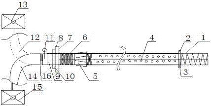
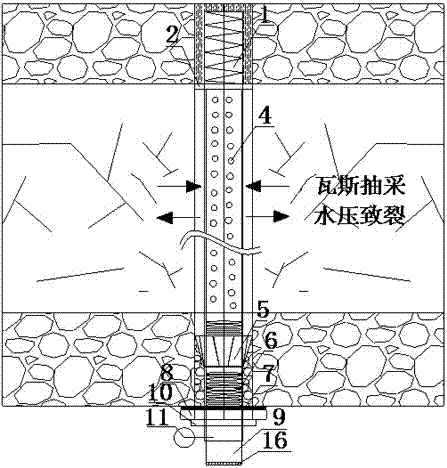
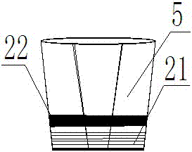
[0028] Such as Figure 1-2 As shown, it is an overall schematic diagram of the bolt system for gas drainage and hydraulic fracturing of the present invention, including a hollow bolt 1, a retaining ring 2, a closed locking device 5, a gas drainage pressure pipe 9, a sealing gasket 7, and a tray 8 , nut 10, hydraulic fracturing system 13 and gas drainage system 15. The anchoring section of the hollow anchor rod 1 is a solid body, with a retaining ring 2 on the outside, a screw hole 3 inside, and threads 6 on the inner and outer surfaces of the tension section; the diameter of the retaining ring 2 is smaller than that of the bolt hole, which is The hollow bolt 1 is a connector in which the solid part of the anchoring section and the hollow gas drainage part of the tensioning section are threaded together; the sealing and locking device 5 is in the shape of a truncated c...


PUM


Abstract

The invention discloses an anchor rod system used for gas extraction and hydraulic fracturing and an extraction method. The anchor rod system comprises a hollow anchor rod, a retaining ring, a closed locking device, a gas extraction pressure pipe, a hydraulic fracturing system, a gas extraction system and the like. The hollow anchor rod comprises an anchoring section and a tensioning section. The anchoring section is a solid body, the retaining ring is arranged outside the anchor section, the diameter of the retaining ring is smaller than that of a drilled hole of the anchor rod, and the retaining ring serves as a connector of the anchoring section solid body and the hollow gas extraction part of the tensioning section. The tensioning section is connected with the closed locking device through an outer thread. The gas extraction pressure pipe is connected in the hollow anchor rod, the diameter of the gas extraction pressure pipe is slightly smaller than that of the hollow anchor rod, and threads are arranged on the upper end and the lower end of the gas extraction pressure pipe to be connected with the hollow anchor rod in a threaded mode. A gas content monitoring instrument is arranged on the lower section of the gas extraction pressure pipe. The gas extraction pressure pipe is connected with a gas extraction pipe of the gas extraction system through a system connecting thread. Gas can be efficiently extracted in an extraction roadway, the hole sealing rate is high, gas extraction intelligence is achieved, and the dangers such as local concentrated gas burst can be effectively pre-warned and predicted.

Description

technical field [0001] The invention belongs to the field of deep gas drainage in coal mines and roadway engineering deformation roadway surrounding rock control field, in particular to a bolt system and a drainage method for gas drainage and hydraulic fracturing. Background technique [0002] When mining gas-bearing coal bodies in deep buried strata, due to the complex geological structure, the gas content and gas pressure gradually increase with the mining depth. As a result, gas disasters often occur, especially coal and gas outburst disasters are becoming more and more serious. The "Coal Mine Safety Regulations" clearly stipulates that new mines with prominent and dangerous coal seams must be pumped first and then built, and the policy of "draining first and then mining, monitoring and monitoring, and determining production according to wind" is implemented. Gas drainage is an effective control method for high-gas mine production, which can not only ensure the safe and ...

Claims


Application Information

Patent Timeline
Patent Type & Authority Applications(China)
IPC IPC(8): E21F7/00E21D21/00E21D20/00E21B43/26E21B47/00E21F17/18
CPCE21B43/26E21B47/00E21D20/003E21D21/0026E21F7/00E21F17/18
Inventor 余伟健吴根水
Owner HUNAN UNIV OF SCI & TECH
Why Eureka
Try Eureka