
Heat pump water heater device

A technology for heat pump water heaters and hot water tanks, which is applied to fluid heaters, lighting and heating equipment, etc., can solve the problems of harsh outdoor operating environment, scaling on the inner wall of the water tank, and decrease in heat exchange rate, so as to improve the use of Energy efficiency and heat transfer effect, retardation and fouling degree, the effect of realizing energy reuse

Inactive Publication Date: 2017-11-17
安徽红叶节能电器科技有限公司
View PDF0 Cites 2 Cited by
  • Summary
  • Abstract
  • Description
  • Claims
  • Application Information

AI Technical Summary

Problems solved by technology

[0003] In the process of using the air source heat pump water heater, if the heating is operated at a low temperature and the outdoor operating environment is harsh, when the temperature of the outer wall of the evaporator of the air source heat pump water heater is lower than 0°C, frost will form on the outer wall of the evaporator, thus Affect the heating effect and its normal operation, and defrosting has become a major problem that bothers users when using air source heat pump water heaters
In the current defrosting method, the defrosting process will produce cold water, which will reduce the temperature of domestic water and affect the user's use effect. Household water generally contains a certain amount of calcium ions and magnesium ions, which is called hard water. Since it has not been softened, long-term use Hard water will cause scaling on the inner wall of the water tank, and the heat transfer rate of the scale is low, resulting in a decrease in the heat transfer rate and reducing the energy efficiency of the whole machine. The condenser usually enlarges the condenser in the system to increase the heating and hot water capacity of the system, but this cannot meet the requirements of large temperature difference and small flow during direct heating operation of the system and small temperature difference and large flow during circulating operation. Requirements, resulting in low heating capacity of the system, which affects the hot water heating capacity of the system

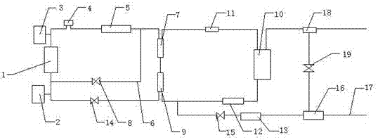
Method used


Image

  • Heat pump water heater device

Examples


Embodiment Construction

[0014] The preferred embodiments of the present invention will be described below in conjunction with the accompanying drawings. It should be understood that the preferred embodiments described here are only used to illustrate and explain the present invention, and are not intended to limit the present invention.

[0015] like figure 1 As shown, a heat pump water heater device includes an evaporator 1, the two sides of the evaporator 1 are respectively provided with an air inlet device 2 and an air outlet device 3, and one side of the evaporator 1 is connected to a gas-liquid-water separator 4 , through the gas-liquid separator 4 to ensure that all of the compressor 5 is gas, so as to ensure that the compressor 5 can operate normally. One side of the gas-liquid-water separator 4 is connected to the compressor 5, and the compressor 5 is Copeland Enthalpy-increasing compressor with supplementary air, the exhaust temperature of the compressor can be reduced by supplementary air, ...


PUM


Abstract

The invention relates to a heat pump water heater device, which includes an evaporator, an air inlet device and an air outlet device are respectively arranged on both sides of the evaporator, and a pipe on one side of the evaporator is connected to a gas-liquid-water separator, and the gas-liquid-water The pipeline on one side of the separator is connected to the compressor, and the compressors are respectively connected to the defrosting pipeline and the first condenser. The defrosting pipeline is provided with a bypass defrosting solenoid valve, and the other end of the defrosting pipeline is connected to the evaporator. The present invention is equipped with a water quality softening device, which softens the usual hard water and then heats it for use, so as to delay and reduce the fouling degree of the inner wall of the water tank, and improve the energy efficiency and heat exchange effect of the heat pump water heater. The condenser meets the requirements of large temperature difference and small flow rate during direct heating operation of the system and small temperature difference and large flow rate during circulating operation. It is equipped with defrosting pipelines to ensure smooth pipelines, realize energy reuse, and ensure water temperature at the same time.

Description

technical field [0001] The invention relates to a heat pump water heater device, which belongs to the technical field of heat pump water heaters. Background technique [0002] With the development of the economy, people have higher and higher requirements for the quality of life, including higher and higher requirements for showering and bathing. Gas water heaters, electric water heaters, and solar water heaters are far from meeting people's requirements for comfort, energy saving and safety. , thus the heat pump water heater came into being. Among them, the air source heat pump water heater is widely used in heat pump water heaters. It is an energy-saving and environmentally friendly hot water supply device that can replace boilers and is not limited by resources. It uses green and pollution-free refrigerants to absorb air The heat, through the work of the compressor, produces domestic hot water above 50 degrees. [0003] In the process of using the air source heat pump w...

Claims


Application Information

Patent Timeline
IPC IPC(8): F24H4/02F24H9/20
CPCF24H4/02F24H9/2007
Inventor 叶连
Owner 安徽红叶节能电器科技有限公司
Learn More