Liquid crystal display device and narrow visual angle waveform self-adaption adjustment method thereof

A liquid crystal display device and self-adaptive adjustment technology, applied in nonlinear optics, instruments, optics, etc., to solve waveform jitter and uneven distribution of points, and facilitate implementation and application.

Active Publication Date: 2017-11-17
KUSN INFOVISION OPTOELECTRONICS
View PDF6 Cites 0 Cited by
  • Summary
  • Abstract
  • Description
  • Claims
  • Application Information

AI Technical Summary

Problems solved by technology

[0005] The main purpose of the present invention is to propose a liquid crystal display device and its narrow viewing angle waveform adaptive adjustment method, aiming to solve the problems existing in the prior art using STV triggering

Method used


Image

  • Liquid crystal display device and narrow visual angle waveform self-adaption adjustment method thereof
  • Liquid crystal display device and narrow visual angle waveform self-adaption adjustment method thereof
  • Liquid crystal display device and narrow visual angle waveform self-adaption adjustment method thereof

Examples


no. 1 example

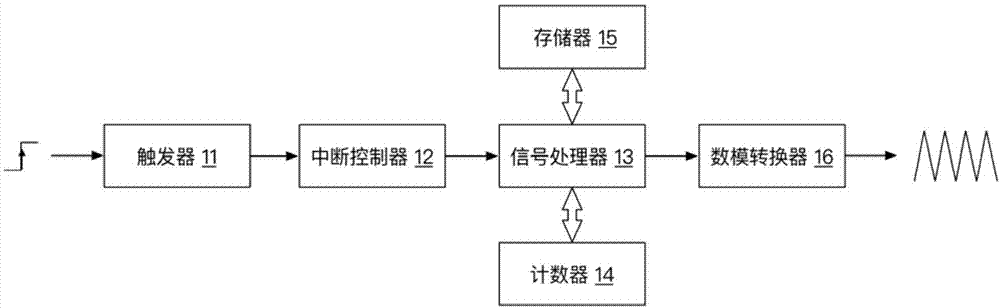
[0040] figure 1 It is a schematic structural diagram of a liquid crystal display device according to an embodiment of the present invention, such as figure 1 As shown, the first embodiment of the present invention provides a liquid crystal display device. The liquid crystal display device includes a trigger 11, an interrupt controller 12, a signal processor 13, a counter 14, a memory 15, a digital-to-analog converter 16 and a display panel (Fig. not shown in);

[0041] Trigger 11, used to detect the trigger signal of the trigger waveform;

[0042] In this embodiment, the trigger signal is a rising edge trigger signal.

[0043] Figure 4 It is a schematic structural diagram of the frame start signal STV and the trigger waveform of the embodiment of the present invention, refer to Figure 4 As shown, in this embodiment, the frequency f1 of the trigger waveform follows the frequency f2 of the frame start signal STV, that is, f1=f2, and the trigger waveform has M trigger signa...

no. 2 example

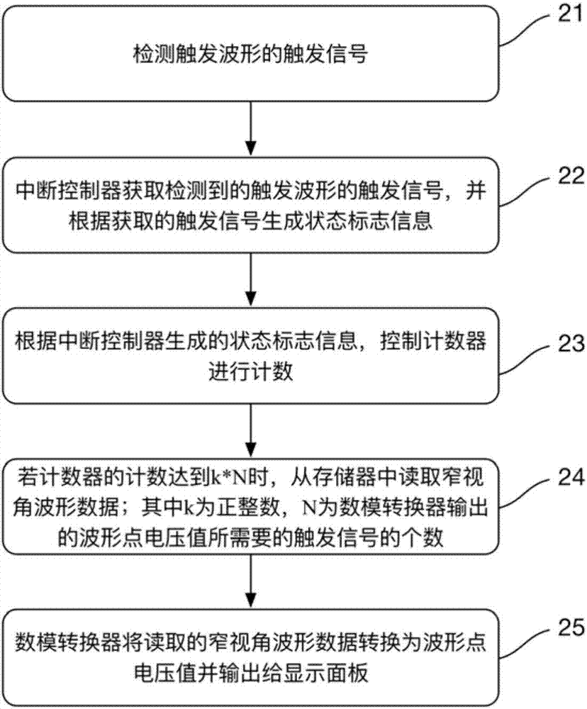
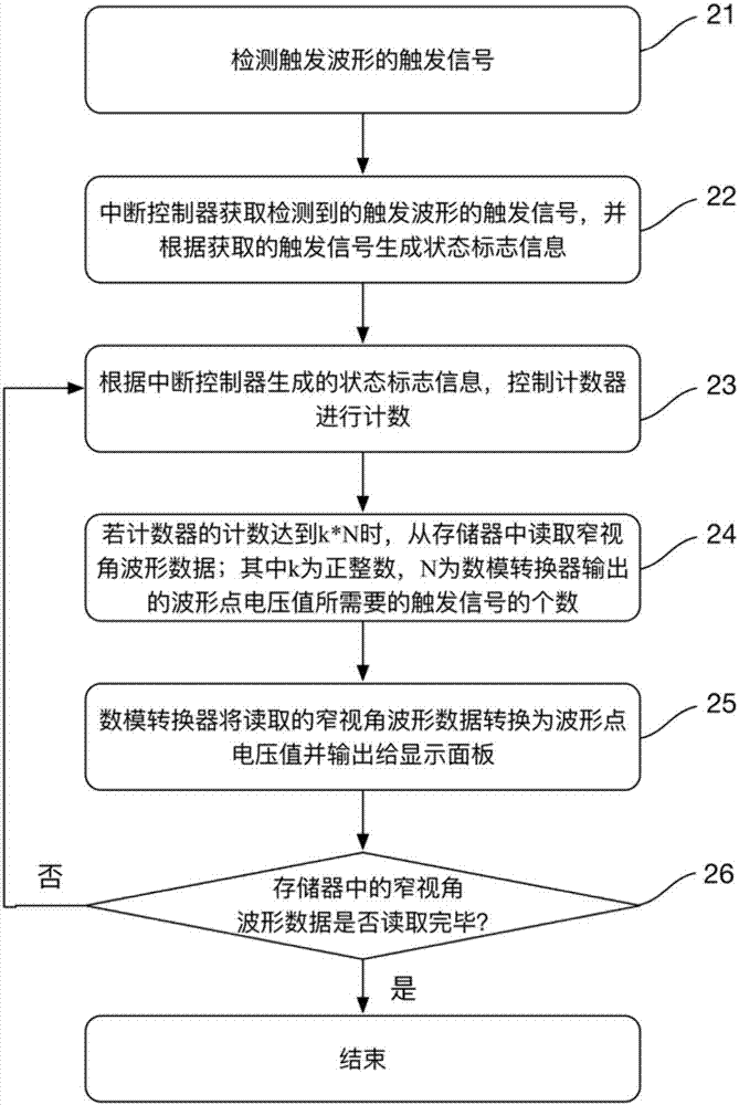
[0058] refer to figure 2 , figure 2 For the second embodiment of the present invention, a narrow viewing angle waveform adaptive adjustment method of a liquid crystal display device is provided. For the liquid crystal display device, reference may be made to the first embodiment, which will not be repeated here. The narrow viewing angle waveform adaptive adjustment method includes steps:

[0059] 21. Detect the trigger signal of the trigger waveform;

[0060] In this embodiment, the trigger signal is a rising edge trigger signal.

[0061] refer to Figure 4 As shown, in this embodiment, the frequency f1 of the trigger waveform follows the frequency f2 of the frame start signal STV, that is, f1=f2, and the trigger waveform has M trigger signals within one period of the frame start signal STV, where M ≥Minimum number of waveform points required for narrow viewing angle.

[0062] It should be noted, Figure 4 The blank area in is not necessary for triggering waveforms.

...


PUM


Abstract

The invention discloses a liquid crystal display device and a narrow visual angle waveform self-adaption adjustment method thereof. The device comprises a trigger, an interrupt controller, a signal processor, a counter, a memorizer, a digital to analog converter and a display panel; the trigger detects trigger signals of a trigger waveform; the interrupt controller generates state mark information according to the obtained trigger signals; the signal processor controls the counter to count according to the state mark information generated by the interrupt controller; when the count of the counter reaches k*N, narrow visual angle waveform data is read from the memorizer, and the read narrow visual angle waveform data is sent to the digital to analog converter; the digital to analog converter receives the narrow visual angle waveform data sent by the signal processor, transforms the received narrow visual angle waveform data to waveform point voltage values and outputs the values to the display panel. According to the liquid crystal display device, the narrow visual angle waveform is adaptively adjusted along with the refresh rate, and the problems of waveform shaking and uneven count distribution caused by automobile allocation algorithm are solved.

Description

technical field [0001] The invention relates to the field of display technology, in particular to a liquid crystal display device and a narrow viewing angle waveform adaptive adjustment method thereof. Background technique [0002] In the prior art, the narrow viewing angle waveform usually uses a frame start signal STV (Start Vertical) as a trigger signal. If the waveform only meets the narrow viewing angle effect at a single frequency, no adaptive adjustment is required; if the waveform needs to meet the narrow viewing angle effect at multiple frequencies, the synchronization signal must be frequency adaptively adjusted along with the trigger signal. Waveform frequency adaptive adjustment can be realized by using STV trigger, but there are the following problems when using STV trigger: [0003] 1) The realization of frequency self-adaptive adjustment usually requires the method of automatic allocation of points, and the number of waveform points required for different fre...

Claims


Application Information

Patent Timeline
Patent Type & Authority Applications(China)
IPC IPC(8): G02F1/13
CPCG02F1/1323
Inventor 荀文东郭晶晶周永超陶子英
Owner KUSN INFOVISION OPTOELECTRONICS
Why Eureka
Try Eureka