Eureka AIR delivers breakthrough ideas for toughest innovation challenges, trusted by R&D personnel around the world.

Smart home engineering box

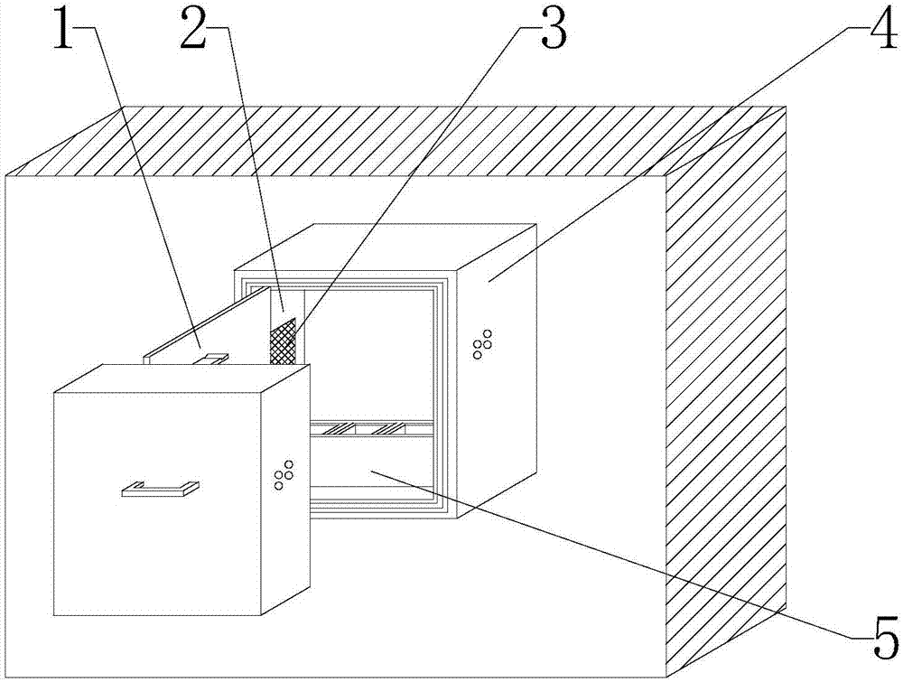
A home engineering box, intelligent technology, applied in the direction of electrical components, substation/power distribution device casing, substation/switchgear cooling/ventilation, etc., can solve the problems of increasing contact resistance, aggravating heat generation, lead wire breakdown and burnout, etc. To achieve the effect of preventing the spread of fire and accelerating the circulation of hot air

Inactive Publication Date: 2017-11-17
阳谷卓伟智能家居有限公司
View PDF0 Cites 3 Cited by
  • Summary
  • Abstract
  • Description
  • Claims
  • Application Information

AI Technical Summary

Problems solved by technology

[0003] In the engineering box, due to the direct sunlight, the reflection of ground heat and the heat generated by the equipment in the box, the internal temperature of the box rises, which can easily cause the insulation aging of the electrical coils and lead wires in the distribution box to break down and burn out. The contact resistance increases due to the high temperature of the contacts, and the increase of the contact resistance aggravates the heat generation. Such a vicious cycle will eventually cause the contacts of the engineering box to burn out. At the same time, the high temperature will also affect the stability of the electrical protection function, the reliability of the operation and the measurement. Because the engineering box is not a fully enclosed box, water droplets can easily enter the box. When water enters the box, it will not only cause damage to the equipment inside the box, but also cause accidents such as box leakage and electric shock. , Due to the narrow space in the home engineering box, the installed equipment lead wires are many and messy, which affects the appearance. When the equipment in the engineering box breaks down, it is not conducive to the maintenance of the engineering personnel. The contact between the lead wires may cause a short circuit. highly prone to fire

Method used


Image

  • Smart home engineering box
  • Smart home engineering box
  • Smart home engineering box

Examples


specific Embodiment approach

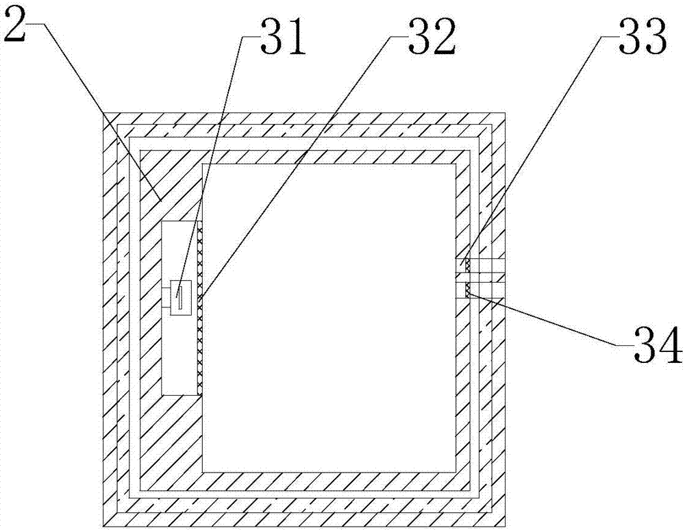
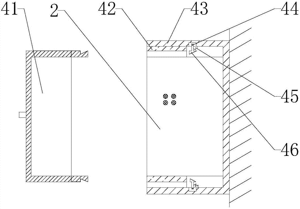
[0028]Specific implementation: the user starts the cooling fan 31, the cooling fan 31 rotates to drive the hot air in the box body 2 to flow, the hot air flowing in the box body 2 moves to the right and enters the inside of the cooling hole 33, and passes through the dustproof net 34 Into the inside of the vent, so as to enter the air outside the waterproof box 43 through the vent. This design can accelerate the circulation of hot air inside the box 2, and prevent dust from entering the inside of the box 2, which solves the problem of excessive temperature in the engineering box. The disadvantages of high damage to the device inside the box.

[0029] The user holds the handle 2 and moves forward. Since the partition box door 51 and the partition box 52 are connected by hinges, the forward movement of the handle drives the partition box door 51 to move forward, and the user places the lead wires of the internal devices of the box body 2 correspondingly. to the inside of the par...


PUM


Abstract

The invention provides a smart home engineering box, which includes a heat dissipation fan, a heat dissipation hole, a waterproof cover, an inflatable water-stop rubber, a waterproof box, a fixing block, a partition box door, a partition box, an intumescent flame-retardant plastic, and a light bulb. The heat dissipation fan is fixed on On the left wall inside the box, there is a cooling hole on the right end of the box. This design can reduce the temperature inside the box. The waterproof cover is set on the front side of the box. The rubber outer end, the box body is fixed inside the waterproof box, the fixed block is set inside the waterproof box, and the fixed block is set on the back side of the expansion waterproof glue. This design can be waterproof. The partition box door is set at the front of the partition box. Intumescent flame-retardant plastic, the bulb is arranged at the bottom of the partition box. This design can prevent the fire from spreading in the partition box. The invention has many functions, is safe and reliable, and has a good heat dissipation effect.

Description

technical field [0001] The invention is a smart home engineering box, which belongs to the technical field of smart home. Background technique [0002] Power distribution box is assembled in closed metal safe by electrical wiring requirement by switchgear, measuring instrument, protective device and auxiliary equipment or on screen width, forms low-voltage power distribution device. During normal operation, the circuit can be connected or disconnected by means of a manual or automatic switch. When a fault or abnormal operation occurs, the circuit is cut off or the alarm is cut off by means of a protective device. It is a general circuit distribution box for all users to use electricity. When a circuit fault occurs, it is beneficial to the maintenance of the circuit. [0003] In the engineering box, due to the direct sunlight, the reflection of ground heat and the heat generated by the equipment in the box, the internal temperature of the box rises, which can easily cause th...

Claims


Application Information

Patent Timeline
Patent Type & Authority Applications(China)
IPC IPC(8): H02B1/56H02B1/28
CPCH02B1/565H02B1/28
Inventor 田煜冰
Owner 阳谷卓伟智能家居有限公司
Why Eureka
Eureka Blog
Learn More