
Various-power-wave output system

A technology of output system and electric power, applied in the field of output system, can solve the problems of poor frequency linearity of output signal, inability to output multiple waveforms, low frequency resolution, etc., achieve large frequency adjustment range, suitable for popularization and use, and simple circuit structure Effect

Inactive Publication Date: 2017-11-17
DEZHOU LINGCHENG POWER SUPPLY CO OF STATE GRID SHANDONG ELECTRIC POWER CO +1
View PDF0 Cites 2 Cited by
  • Summary
  • Abstract
  • Description
  • Claims
  • Application Information

AI Technical Summary

Problems solved by technology

[0002] In modern society, in the design, debugging and electronic test process of signal processing, communication field and automation control system, sine wave signal, rectangular wave signal and triangular wave signal are often required as signal source or other purposes, and automation Technology has already penetrated into various fields of social production. Signal generators with high precision, wide frequency and high stability play a vital role in improving and improving the performance of the overall system. Traditional function signal waveform generators such as 8098 etc., usually made of discrete components such as transistors and op-amp ICs. The function generator composed of discrete components has a simple structure and is easy to manufacture, but it is usually a single function generator with a low frequency and a single output waveform. Output a variety of waveforms, and the output signal has disadvantages such as poor frequency linearity, low frequency stability, low frequency resolution, relatively long frequency conversion time, and large phase noise.

Method used


Image

  • Various-power-wave output system
  • Various-power-wave output system

Examples


Embodiment Construction

[0013] The following will clearly and completely describe the technical solutions in the embodiments of the present invention with reference to the accompanying drawings in the embodiments of the present invention. Obviously, the described embodiments are only some of the embodiments of the present invention, not all of them. Based on the embodiments of the present invention, all other embodiments obtained by persons of ordinary skill in the art without making creative efforts belong to the protection scope of the present invention.

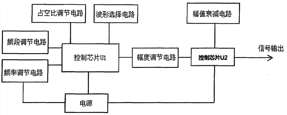
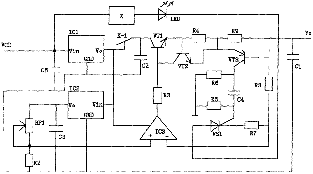
[0014] see Figure 1~2 , in an embodiment of the present invention, a variety of power wave output systems, including a control chip U1, a control chip U2, a frequency band adjustment circuit, a frequency adjustment circuit, and an amplitude adjustment circuit, and the control chip U1 is respectively connected to a duty ratio adjustment circuit, Waveform selection circuit, frequency band adjustment circuit, frequency adjustment circuit, power sup...


PUM


Abstract

The invention discloses a variety of power wave output systems, including a control chip U1, a control chip U2, a frequency band adjustment circuit, a frequency adjustment circuit and an amplitude adjustment circuit. The control chip U1 is respectively connected to a duty cycle adjustment circuit, a waveform selection circuit, and a frequency band adjustment circuit The adjustment circuit, the frequency adjustment circuit, the power supply and the amplitude adjustment circuit, the amplitude adjustment circuit is also connected to the control chip U2, and the control chip U2 is also connected to the power supply, the amplitude attenuation circuit and the signal output terminal respectively. The system of the invention uses the chip ICL8038 as the core device, which can output square waves, triangle waves and sine waves at the same time, has a large frequency adjustment range, small waveform distortion, strong practicability, simple circuit structure and low cost, and is very suitable for popularization and use.

Description

technical field [0001] The invention relates to an output system, in particular to a multiple electric wave output system. Background technique [0002] In modern society, in the design, debugging and electronic test process of signal processing, communication field and automation control system, sine wave signal, rectangular wave signal and triangular wave signal are often required as signal source or other purposes, and automation Technology has already penetrated into various fields of social production. Signal generators with high precision, wide frequency and high stability play a vital role in improving and improving the performance of the overall system. Traditional function signal waveform generators such as 8098 etc., usually made of discrete components such as transistors and op-amp ICs. The function generator composed of discrete components has a simple structure and is easy to manufacture, but it is usually a single function generator with a low frequency and a s...

Claims


Application Information

Patent Timeline
IPC IPC(8): H03K19/082H03K4/06H03K3/80
CPCH03K19/082H03K3/80H03K4/06
Inventor 王富良杨雪李娜
Owner DEZHOU LINGCHENG POWER SUPPLY CO OF STATE GRID SHANDONG ELECTRIC POWER CO
Learn More