Paper cone for sound system

A sound system and paper cone technology, applied in the direction of diaphragm structure, planar diaphragm, diaphragm extension, etc., can solve the problems of increased manufacturing cost, coil heating and burning, and increased number of paper cone connecting parts, so as to save assembly cost, Reduce the bonding area and avoid the effect of heat and burnout

Inactive Publication Date: 2017-11-17
饶名梅
View PDF0 Cites 1 Cited by
  • Summary
  • Abstract
  • Description
  • Claims
  • Application Information

AI Technical Summary

Problems solved by technology

[0002] In the audio system, the voice coil will generate strong vibration in the magnetic field after the signal is connected. The voice coil is fixed on the paper cone, and the vibration of the voice coil drives the vibration of the paper cone. The paper cone used in the audio system currently on the market Various, although it can meet the basic pronunciation effect, there are still many defects. For example, with the high power of audio equipment in recent years, a sound system with high input resistance is required. When adding input signals to the sound system, When a current flows through the coil part of the voice coil, the coil part will generate heat due to its resistance, and this heat will be dissipated by the voice coil frame, the magnetic gap part, etc., but if an excessive input signal is applied to the audio system If there is no sufficient heat dissipation effect, it is easy to cause the coil to heat up and burn out. The traditional audio system paper cone must be installed with a dust cover, which leads to more connecting parts of the paper cone, and at the same time brings a burden on the assembly of the paper cone and increases manufacturing cost

Method used


Image

  • Paper cone for sound system
  • Paper cone for sound system
  • Paper cone for sound system

Examples


Embodiment Construction

[0018] In order to make the technical means, creative features, goals and effects achieved by the present invention easy to understand, the present invention will be further described below in conjunction with specific illustrations.

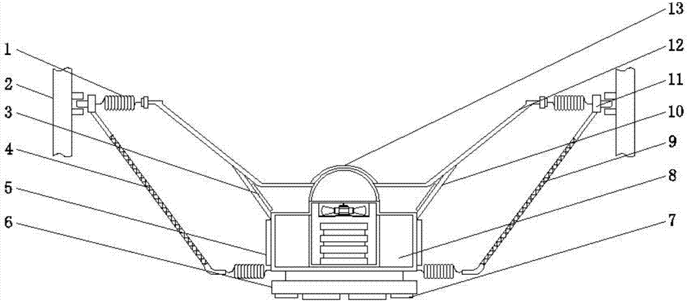
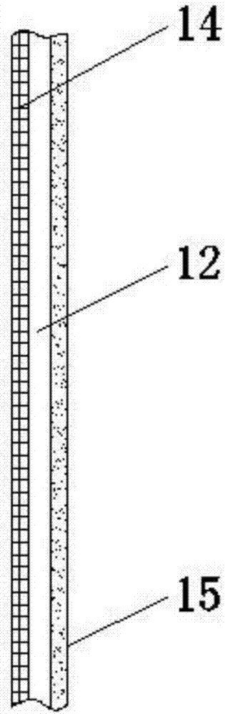
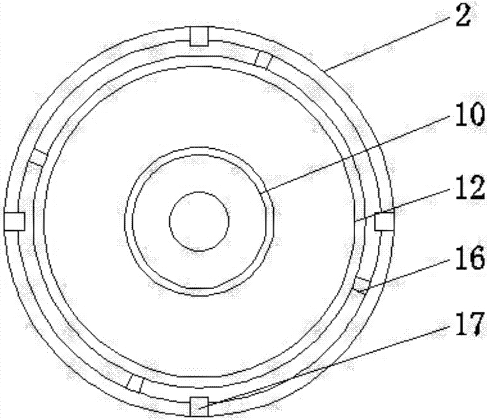
[0019] Such as Figure 1 to Figure 4 As shown, a paper cone for an audio system includes a membrane 3, a paper cone protection frame 4, a mounting flange 6 and a diaphragm 12, and the bottom of the mounting flange 6 is provided with installation limit holes of different sizes 7, so that it is possible to install the paper cones inside different paper cone installation frames, the top of the mounting flange 6 is evenly installed with a second return spring 21, and the end of the second return spring 21 away from the installation flange 6 is installed with a paper cone protection Frame 4, both sides of the paper cone protection frame 4 are evenly provided with ventilation holes 9 to assist in dissipating the excessive heat generated by the coil, a...


PUM


Abstract

The invention relates to a paper cone for an audio system, which includes a membrane, a paper cone protection frame, a mounting flange and a diaphragm. The top of the mounting flange is uniformly equipped with a second return spring, and the second return spring is far away from the One end of the installation flange is installed with a paper cone protection frame, the top of the installation flange is provided with a cooling groove, and the inner center of the cooling groove is provided with a voice coil installation groove, and a sound coil is installed inside the voice coil installation groove. lock up. In the present invention, a drum is installed at the bottom of the diaphragm and a connecting groove is provided at the connection between the diaphragm and the voice coil. The drum just protects the voice coil and prevents dust from entering the magnetic gap. There is no need to install a dust cover, which saves parts. The assembly cost is reduced, and the bonding area is reduced, and the product quality is improved.

Description

technical field [0001] The invention relates to the technical field of audio equipment, in particular to a paper cone used in an audio system. Background technique [0002] In the audio system, the voice coil will generate strong vibration in the magnetic field after the signal is connected. The voice coil is fixed on the paper cone, and the vibration of the voice coil drives the vibration of the paper cone. The paper cone used in the audio system currently on the market Various, although it can meet the basic pronunciation effect, there are still many defects. For example, with the high power of audio equipment in recent years, a sound system with high input resistance is required. When adding input signals to the sound system, When a current flows through the coil part of the voice coil, the coil part will generate heat due to its resistance, and this heat will be dissipated by the voice coil frame, the magnetic gap part, etc., but if an excessive input signal is applied t...

Claims


Application Information

Patent Timeline
Patent Type & Authority Applications(China)
IPC IPC(8): H04R7/04
CPCH04R7/04H04R2207/021
Inventor 饶名梅顾杰
Owner 饶名梅
Why Eureka
Try Eureka