Laser polishing machine and polishing method using same

A laser polishing and laser light source technology, which is applied in the field of laser polishing machines, can solve problems such as unevenness and insufficient melting of the workpiece surface

Inactive Publication Date: 2017-11-21
佘志荣
View PDF6 Cites 8 Cited by
  • Summary
  • Abstract
  • Description
  • Claims
  • Application Information

AI Technical Summary

Problems solved by technology

However, it is easy to cause insufficient melting on the surface of the workpiece to form small holes, and cannot smooth the rough surface

Method used


Image

  • Laser polishing machine and polishing method using same
  • Laser polishing machine and polishing method using same
  • Laser polishing machine and polishing method using same

Examples


Embodiment Construction

[0020] In order to make the technical problems, technical solutions and beneficial effects to be solved by the present invention clearer and clearer, the present invention will be further described in detail below in conjunction with the accompanying drawings and embodiments. It should be understood that the specific embodiments described here are only used to explain the present invention, not to limit the present invention.

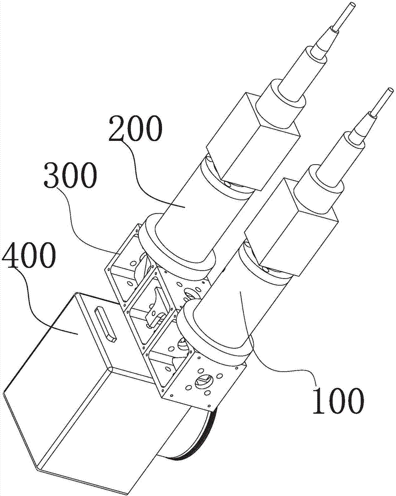
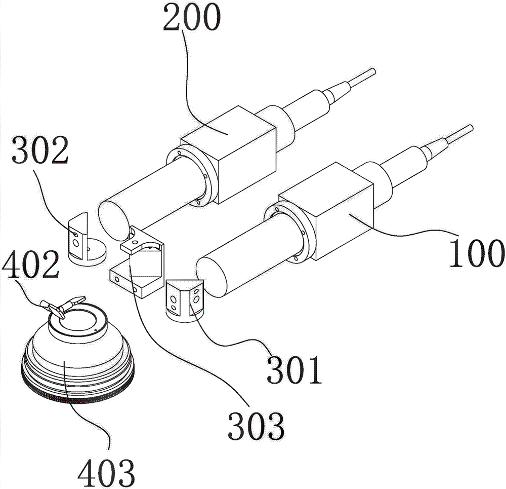
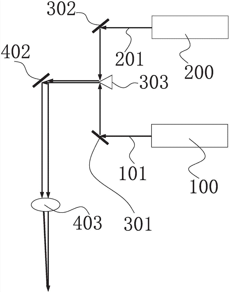
[0021] Please refer to Figure 1 to Figure 6 As shown, a laser polishing machine is described below in conjunction with an embodiment, which includes a first group of laser light source systems 100 , a second group of laser light source systems 200 , a light combining prism system 300 , and a laser scanning system 400 . The laser scanning system 400 is installed at the common end of the first group of laser light source systems 100 and the second group of laser light source systems 200, and the described light-combining prism system 300 is installed at ...


PUM

PropertyMeasurementUnit
wavelengthaaaaaaaaaa
frequencyaaaaaaaaaa
wavelengthaaaaaaaaaa

Abstract

The invention relates to a laser polishing machine. The laser polishing machine comprises a first group of laser light source systems, a second group of laser light source systems, a light integrating prism system, a laser scanning system and a filed lens, wherein the laser scanning system is mounted at a common end of the first group of laser light source systems and the second group of laser light source systems; the light integrating prism system is mounted between the first group of laser light source systems and the second group of laser light source systems; the light integrating prism system comprises a first group of reflecting mirrors, a second group of reflecting mirrors and a prism used for integrating light; the laser scanning system comprises a laser scanning galvanometer; and a first group of reflecting mirrors, a second group of reflecting mirrors as well as the light integrating prism system are positioned on the same horizontal line. During working, the light integrating prism system is utilized for integrating laser generated by the first group of laser light source systems and the second laser light source systems into a laser light beam, and the laser light beam is focused on the surface of a workpiece for being repeatedly subjected to laser scanning polishing treatment under co-action of the laser scanning galvanometer and the field lens, so that a metal workpiece surface with high smoothness and high degree of finish is conveniently processed out.

Description

【Technical field】 [0001] The invention relates to a laser polishing machine used for polishing the surface of a workpiece and a polishing method using the laser machine. 【Background technique】 [0002] The commonly used laser polishing is to use the method of metal remelting. There is a continuous wave laser for macro laser polishing (Macro Laser Polishing), and a pulse laser for micro laser polishing (Micro Laser Polishing). Although the laser polishing method can achieve better flatness, such as continuous laser polishing, it is easy to cause deformation of the workpiece, poor finish, and scratches. Although the pulse laser polishing method can achieve a better finish. However, it is easy to cause insufficient melting on the surface of the workpiece to form small holes, and it cannot smooth the rough surface. 【Content of invention】 [0003] In view of this, the technical problem to be solved by the present invention is to provide a laser polishing machine capable of pr...

Claims


Application Information

Patent Timeline
Patent Type & Authority Applications(China)
IPC IPC(8): B23K26/352B23K26/064
CPCB23K26/352B23K26/0643B23K26/0652
Inventor 佘志荣谢永灵
Owner 佘志荣
Why Eureka
Try Eureka