
Gas-liquid separator welding fixture and application method thereof

A gas-liquid separator and welding tooling technology, applied in the field of tooling and fixtures, can solve the problems of low positioning accuracy, fixation, and inability to realize the inlet pipe and outlet pipe, etc., and achieve the effect of high-precision positioning

Active Publication Date: 2017-11-21
ANHUI ZHONGHUI REFRIGERATION
View PDF11 Cites 7 Cited by
  • Summary
  • Abstract
  • Description
  • Claims
  • Application Information

AI Technical Summary

Problems solved by technology

[0007] The present invention provides a gas-liquid separator welding tool, the purpose of which is to solve the movable clamping structure of the welding fixture of the existing gas-liquid separator. It is inconvenient to fix the outlet pipe, the positioning accuracy is low, and the fixation is not firm enough, and the elbow section of the intake pipe will be stuck between the rotating semi-circle support block and the semi-circle support block, resulting in the failure of the rotation semi-circle support block and the semi-circle support block. Together, the problem of fixing the inlet pipe and the outlet pipe cannot be realized. This tooling can complete the welding of the gas-liquid separator with high efficiency and high precision.

Method used


Image

  • Gas-liquid separator welding fixture and application method thereof
  • Gas-liquid separator welding fixture and application method thereof
  • Gas-liquid separator welding fixture and application method thereof

Examples


Embodiment 1

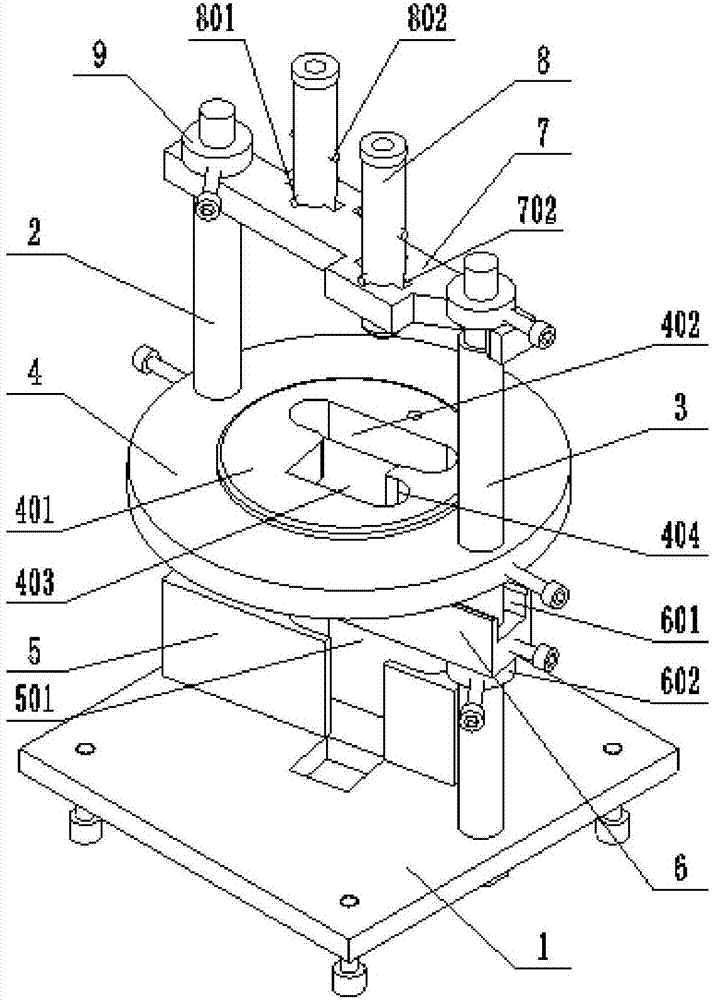
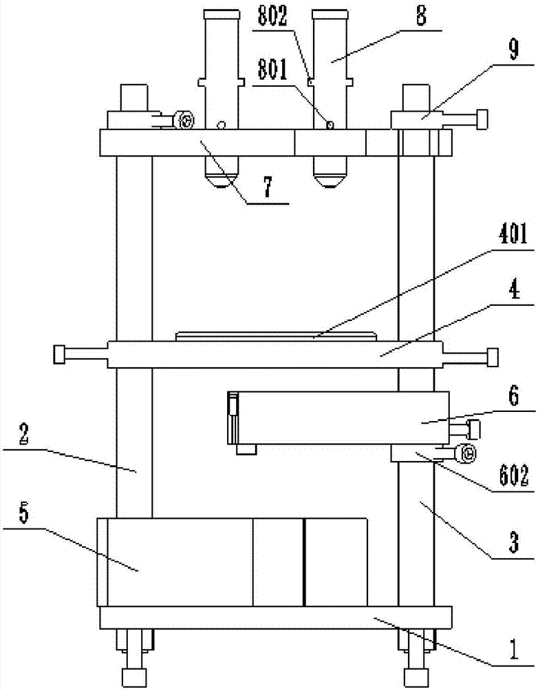
[0052] like figure 2 , image 3 , Figure 4 As shown, this embodiment provides a gas-liquid separator welding tool, which mainly includes a bottom plate 1 , a guide positioning plate 4 , a limit baffle 5 and a support plate 6 .

[0053] Wherein, the bottom four corners of the base plate 1 are respectively provided with a leveling screw for adjusting the flatness of the base plate 1, and the base plate 1 is provided with two vertical cylindrical columns, which are respectively the first column 2 and the second column. Column 3, the lower end of the column is threadedly connected with the base plate 1. The guide positioning plate 4 is provided with two guide holes respectively matched with the two columns, the guide positioning plate 4 is sleeved on the two columns through the guide holes, and the outer side of the guide hole is provided with a connected threaded hole through which the screw passes. The threaded hole can stretch into the guide hole, so that the surface of th...


PUM


Abstract

The invention discloses a gas-liquid separator welding fixture and an application method thereof, and belongs to the field of fixtures. The fixture comprises a bottom plate, a guide positioning disc, a limiting baffle and a support plate, wherein two upright posts are arranged on the bottom plate; the guide positioning disc is arranged on the two uprights in a sleeving way, and a first kidney-shaped hole and a positioning hole which penetrate through the upper and lower surfaces are formed in the guide positioning disc; the limiting baffle and the support plate are both positioned below the guide positioning disc; a second kidney-shaped hole corresponding to the first kidney-shaped hole is formed in the limiting baffle; a positioning slot corresponding to the positioning hole is formed in the upper surface of the support plate; a protection gas pipe seat is mounted above the guide positioning disc; two protection gas pipes are fixed, and correspond to the first kidney-shaped hole and the positioning hole respectively. The fixture disclosed by the invention can finish welding of a gas-liquid separator with high efficiency and high precision; moreover, oxidation caused by high temperature of welding can be avoided, and acid pickling after welding is omitted. The application method disclosed by the invention can be used for positioning a gas inlet pipe, a gas outlet pipe and an upper end cover with high efficiency and high precision to finish welding of the gas-liquid separator.

Description

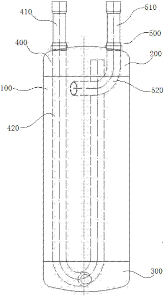
technical field [0001] The invention belongs to the field of tooling fixtures, and relates to a tooling fixture used in the welding process of a gas-liquid separator, more specifically, to a welding tooling for a gas-liquid separator and a use method thereof. Background technique [0002] The gas-liquid separator is a device that separates the small liquid droplets condensed in the saturated gas to achieve the purpose of condensate recovery or gas phase purification. The gas-liquid separator installed between the suction end of the compressor and the evaporator of the air-conditioning refrigeration system can be used to temporarily store the return liquid of the system, control the return of liquid refrigerant and lubricating oil to the compressor at a safe speed, and avoid hydraulic shock , It can also play the role of filtration and oil return. [0003] like figure 1 As mentioned above, the gas-liquid separator generally includes a cylinder body 100, an upper end cap 200...

Claims


Application Information

Patent Timeline
IPC IPC(8): B23K37/053
CPCB23K37/0533
Inventor 潘新阳李洪洋徐金超
Owner ANHUI ZHONGHUI REFRIGERATION
Learn More