
Closed rectangular-section FRP stirrup and manufacturing method thereof

A technology with a rectangular cross-section and a manufacturing method, which is applied to structural elements, building components, building reinforcements, etc., can solve problems such as bond-slip damage and low strength of the bending section of FRP stirrups, and achieve stress concentration relief and superior restraint , the effect of avoiding the corrosion of steel bars

Inactive Publication Date: 2017-11-21
HARBIN INST OF TECH
View PDF8 Cites 2 Cited by
  • Summary
  • Abstract
  • Description
  • Claims
  • Application Information

AI Technical Summary

Problems solved by technology

[0005] In order to solve the problems of the low strength of the bending section of the circular cross-section FRP stirrup prepared by the existing traditional pultrusion molding process and the problem that the lap connection mode is easy to cause bond-slip damage, the present invention further proposes a closed rectangular cross-section FRP stirrup and its production method

Method used


Image

  • Closed rectangular-section FRP stirrup and manufacturing method thereof
  • Closed rectangular-section FRP stirrup and manufacturing method thereof
  • Closed rectangular-section FRP stirrup and manufacturing method thereof

Examples


specific Embodiment approach 1

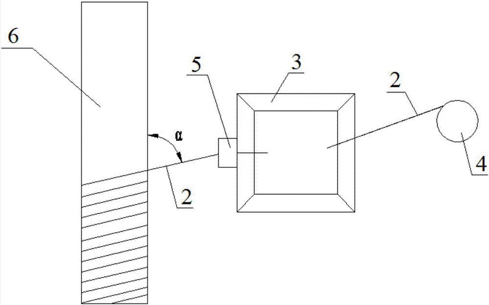
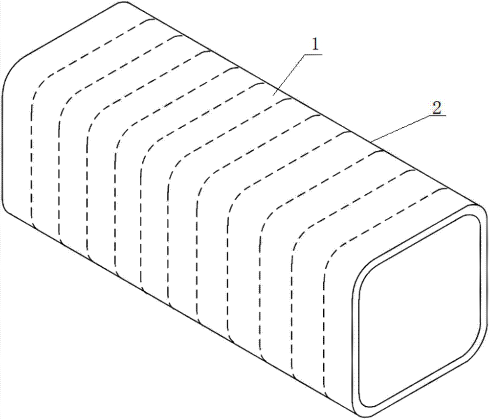
[0034] Specific implementation mode one: combine Figure 3 to Figure 11 To illustrate this embodiment, a closed rectangular cross-section FRP stirrup described in this embodiment includes a stirrup body 1, and the stirrup body 1 is formed by winding FRP bundles 2 impregnated with resin layer by layer along the circumferential direction of the stirrup. The cross-sectional shape of the body 1 along the direction perpendicular to the perimeter is rectangular.

specific Embodiment approach 2

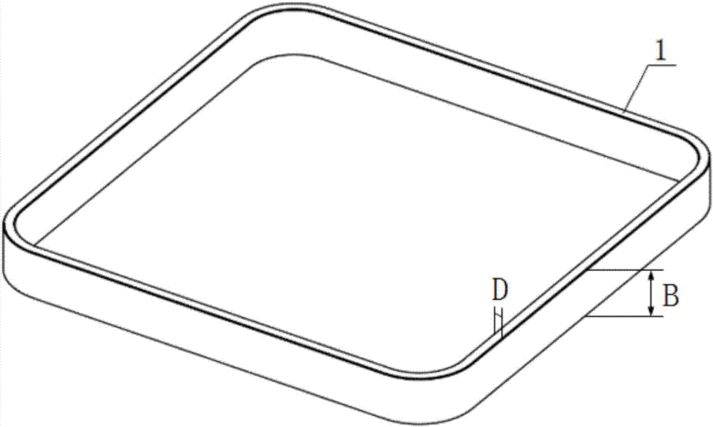
[0035] Specific implementation mode two: combination Figure 3 to Figure 11 To illustrate this embodiment, the thickness D of the rectangular cross section of the stirrup body 1 in this embodiment is 3 mm to 10 mm, and the width B of the rectangular cross section of the stirrup body 1 is 10 mm to 30 mm. The undisclosed technical features in this embodiment are the same as those in the first embodiment.

[0036] In this embodiment, the thickness D of the rectangular cross-section of the stirrup body 1 and the range value of the width B of the rectangular cross-section of the stirrup body 1 are all commonly used optimal range values, which can be selected according to actual needs in the actual application process, and Not limited to the above range values.

specific Embodiment approach 3

[0037] Specific implementation mode three: combination Figure 3 to Figure 11 To illustrate this embodiment, the cross-sectional shape of the stirrup body 1 in this embodiment along the circumferential direction is a closed circle, rhombus or rectangle. The undisclosed technical features in this embodiment are the same as those in the first or second specific embodiment.

[0038] The circle in this embodiment includes an ellipse, and the rectangle includes a square.

[0039] The stirrup body 1 described in this embodiment is formed by sequentially winding FRP bundles 2 without overlapping sections. Its rectangular cross-sectional area and aspect ratio can be selected according to actual needs. For the rectangular closed rectangular section FRP stirrups, the chamfer radius and thickness ratio can be determined according to the molding process, actual construction feasibility and mechanical performance requirements. When used in combination, the stirrup bodies 1 of different ...


PUM

PropertyMeasurementUnit
Thicknessaaaaaaaaaa
Widthaaaaaaaaaa

Abstract

The invention provides a closed rectangular-section FRP stirrup and a manufacturing method thereof, and relates to the technical field of building and bridge structures. By adoption of the closed rectangular-section FRP stirrup and the manufacturing method thereof, the problems that the bent section of a round-section FRP stirrup manufactured through a traditional pultrusion forming technique is low in strength, and bonding and sliding damage is likely to be caused by a lap joint method are solved. The closed rectangular-section FRP stirrup comprises a stirrup body, wherein the stirrup body is formed by winding an FRP bundle adopting infiltration resin in the perimeter direction layer by layer, and the cross section, in the direction perpendicular to the perimeter direction, of the stirrup body is rectangular. The manufacturing method of the closed rectangular-section FRP stirrup comprises the steps of glue dipping, winding, curing, demolding and cutting. The closed rectangular-section FRP stirrup and the manufacturing method thereof are used for building concrete construction.

Description

technical field [0001] The invention relates to a closed rectangular section FRP stirrup and a manufacturing method thereof. Background technique [0002] Reinforced concrete structures are currently the most widely used civil engineering structures, consisting of steel bars as reinforcing materials and a concrete matrix. Under the action of environmental factors such as temperature, humidity, carbon dioxide gas, and chloride ions, the decrease in the alkalinity inside the concrete will cause corrosion of the steel bars, and the volume expansion of the corrosion products will lead to tensile cracking of the concrete protective layer. Under the combined action of corrosive media and stress, The intensified corrosion of steel bars and the obvious degradation of mechanical properties eventually lead to the early loss of use of reinforced concrete structures before reaching the design reference period, especially factory buildings, bridges and marine structures exposed to aggres...

Claims


Application Information

Patent Timeline
IPC IPC(8): E04C5/07B29C70/34
CPCE04C5/07B29C70/34E04C5/073
Inventor 王震宇董恒磊王代玉
Owner HARBIN INST OF TECH
Learn More